EasyManuals Logo

Omron G5 Series User Manual

Omron G5 Series
506 pages
To Next Page IconTo Next Page
To Previous Page IconTo Previous Page
Page #32 background imageLoading...
Page #32 background image
1 Features and System Configuration
1 - 4
OMNUC G5-series (Pulse-train Input Type) AC Servomotors and Servo Drives User’s Manual
1-3 Names and Functions
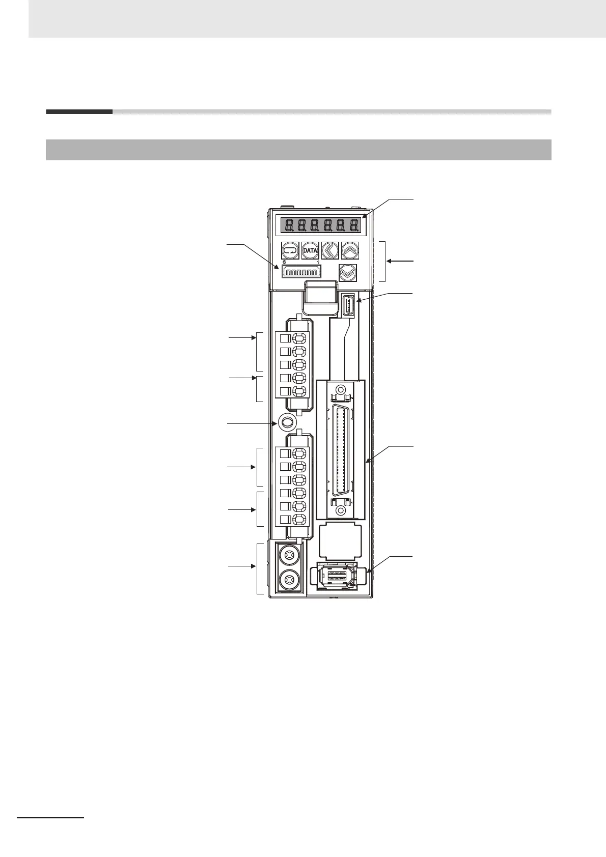
1-3-1 Servo Drive Part Names
Display
Operation area
USB connector (CN7)
Control I/O connector (CN1)
Encoder connector (CN2)
Analog monitor connector
(CN5)
Main circuit power supply
terminals
(L1, L2, and L3)
Control circuit power supply
terminals
(L1C and L2C)
Charge Lamp
External regeneration resistor
connection terminals
(B1, B2, and B3)
Motor connection terminals
(U, V, and W)
Protective ground terminals

Table of Contents

Other manuals for Omron G5 Series

Questions and Answers:

Question and Answer IconNeed help?

Do you have a question about the Omron G5 Series and is the answer not in the manual?

Omron G5 Series Specifications

General IconGeneral
FeedbackIncremental Encoder, Absolute Encoder
CommunicationEtherCAT
Safety FunctionSTO (Safe Torque Off)
Protection FunctionsOvervoltage, Undervoltage, Overcurrent
Vibration Resistance4.9 m/s² (10 to 55 Hz)

Related product manuals