6 - 7
6 Applied Functions
OMNUC G5-series (Pulse-train Input Type) AC Servomotors and Servo Drives User’s Manual
6-2 Adaptive Filter
6
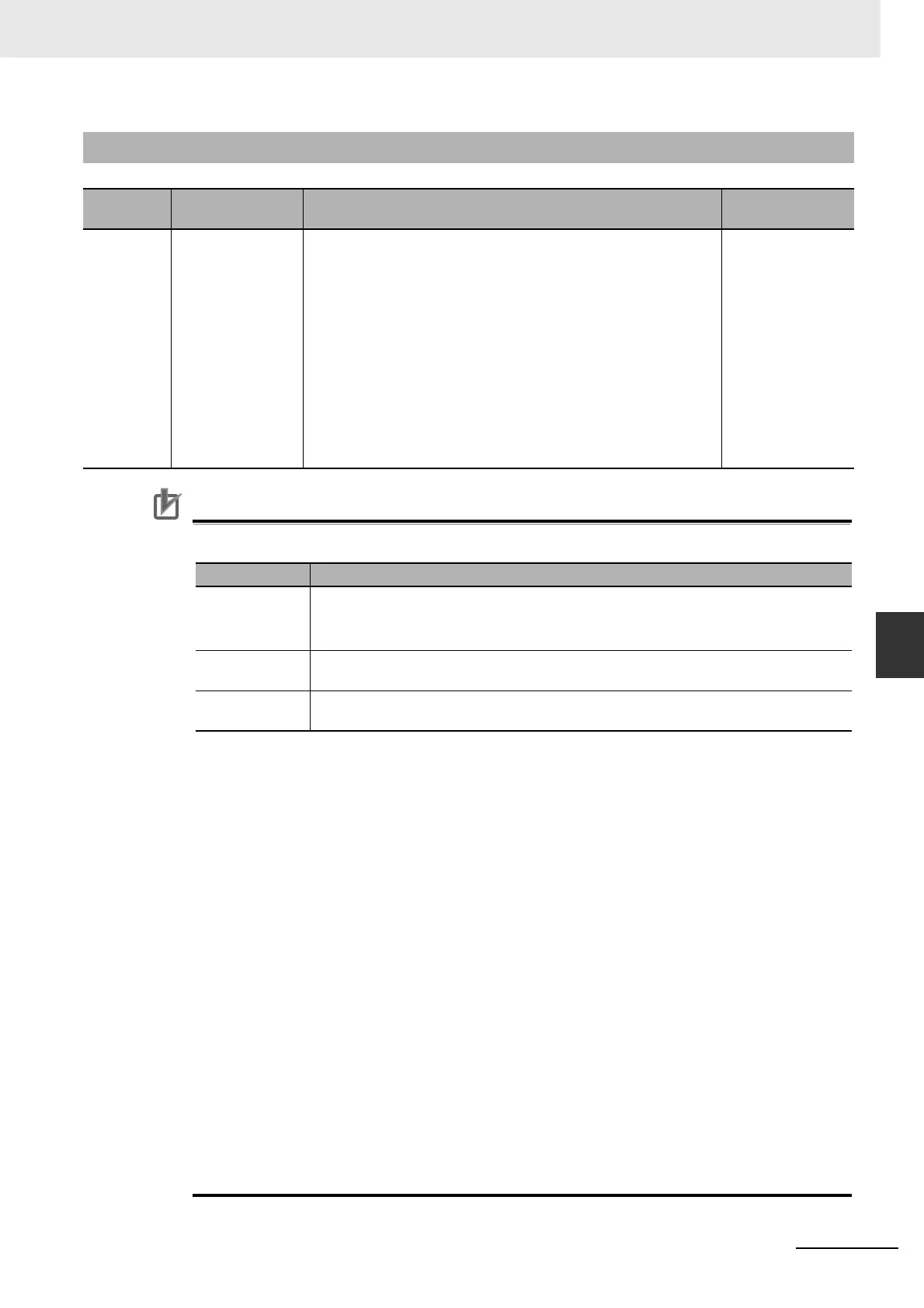
6-2-2 Parameters Requiring Settings
Precautions for Correct UsePrecautions for Correct Use
• Adaptive filter may not operate correctly under the following conditions.
• If the adaptive filter does not operate properly, use Notch 1 (Pn201 to Pn203) or Notch 2
(Pn204 to Pn206) parameters to implement resonance measures according to the manual
adjustment procedure.
Refer to 6-3 Notch Filters on page 6-8 for details about the notch filter.
• An unusual noise or vibration may occur until the adaptive filter stabilizes after startup,
immediately after the first servo ON, or when the value set in Realtime Autotuning Machine
Rigidity Setting (Pn003) is increased. This is not a problem if it disappears right away. If the
vibration or unusual noise, however, continues for three or more reciprocating operations, take
the following measures in the possible order.
• Write the parameters used during normal operation to the EEPROM.
• Lower the value set in Realtime Autotuning Machine Rigidity Setting (Pn003).
• Disable the adaptive filter by setting Adaptive Filter Selection (Pn200) to 0.
(Resetting of inertial estimation and adaptive operation)
• Manually set the notch filter.
• If unusual noise or vibration occurs, the setting of Notch 3 (Pn207 to Pn209) or Notch 4
(Pn210 to Pn212) may have changed to an extreme value. In this case, set Adaptive Filter
Selection (Pn200) to 0 to disable the parameter and then set Notch 3 Frequency Setting
(Pn207) and Notch 4 Frequency Setting (Pn210) to 5,000 (disabled). Next, enable Adaptive
Filter Selection again.
• Notch 3 Frequency Setting (Pn207) and Notch 4 Frequency Setting (Pn210) are written to the
EEPROM every 30 minutes. When the power supply is turned OFF and then turned ON again,
this data is used as the default settings to perform adaptive operation.
6-2-2 Parameters Requiring Settings
Parameter
No.
Name Description Reference
Pn200 Adaptive Filter
Selection
Set the number of resonance frequencies to be estimated by the
adaptive filter and the operation to be performed after estimation.
0: Adaptive filter disabled
1: One adaptive filter enabled
2: Two adaptive filters enabled
3: Resonance frequency measurement mode
When the influence of a resonance point appears in the motor
speed, parameters related to notch filter 3 and 4 are set
automatically according to the number of adaptive filters.
4: Adaptive result cleared
Parameters related to notch filter 3 and 4 are disabled and the
adaptive result is cleared.
P. 7 - 2 0
Item Conditions that interfere with the adaptive filter
Resonance
points
• If the resonance frequency is 300 Hz or lower
• If the resonance peak or control gain is too low to affect the motor speed
• If there are three or more resonance points
Load • If the motor speed with high-frequency components changes due to backlash or
other non-linear elements
Command
pattern
• If the acceleration/deceleration is 3,000 r/min/s or higher

 Loading...


