4 - 43
4 System Design
OMNUC G5-series (Pulse-train Input Type) AC Servomotors and Servo Drives User’s Manual
4-4 Regenerative Energy Absorption
4
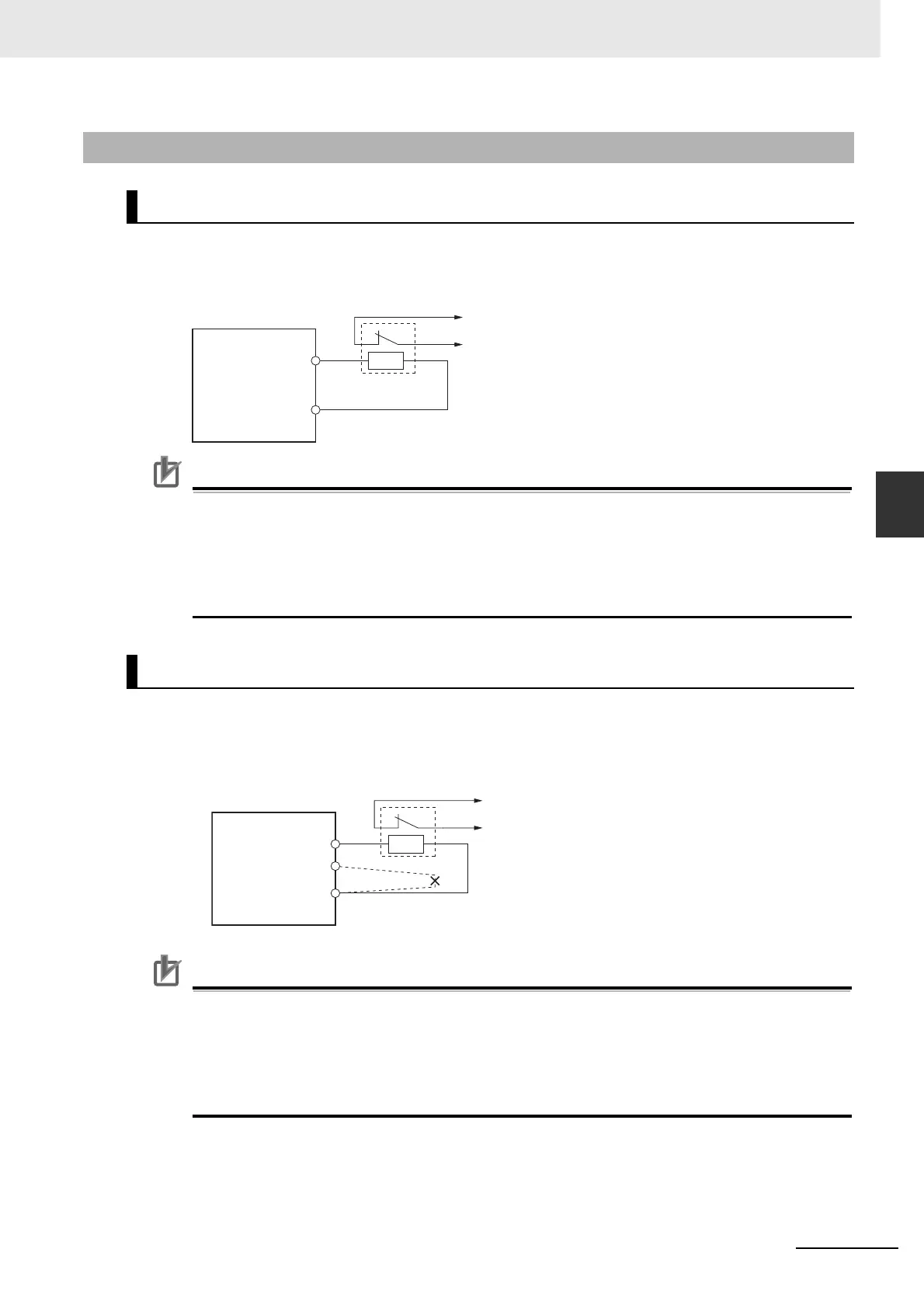
4-4-4 Connecting an External Regeneration Resistor
Normally B2 and B3 are open.
If an External Regeneration Resistor is necessary, connect the External Regeneration Resistor
between B1 and B2 as shown in the diagram below.
Precautions for Correct UsePrecautions for Correct Use
Connect the thermal switch output so that the main circuit power supply is shut OFF when the
contacts open.
When using multiple External Regeneration Resistors, connect each thermal switch in series.
Fire or burn damage may result due to the temperature rise in the resistors if the Servo Drive is
used without setting up a power supply shutoff sequence using the output from the thermal
switch.
Normally B2 and B3 are shorted.
If an External Regeneration Resistor is necessary, remove the short-circuit bar between B2 and B3,
and then connect the External Regeneration Resistor between B1 and B2 as shown in the diagram
below.
Precautions for Correct UsePrecautions for Correct Use
Connect the thermal switch output so that the main circuit power supply is shut OFF when the
contacts open.
When using multiple External Regeneration Resistors, connect each thermal switch in series.
Fire or burn damage may result due to the temperature rise in the resistors if the Servo Drive is
used without setting up a power supply shutoff sequence using the output from the thermal
switch.
4-4-4 Connecting an External Regeneration Resistor
R88D-KP01H/-KP02H/-KP04H
R88D-KP08H/-KP10H/-KP15H/-KP20H/-KP30H/-KP50H/
Servo Drive
B1
External
Regeneration
Resistor
θ>
Thermal switch output
B2
B1
B3
Remove the short-circuit bar
between B2 and B3.
θ>
B2
Servo Drive
External
Regeneration
Resistor
Thermal switch output

 Loading...


