7 - 53
7 Parameter Details
OMNUC G5-series (Pulse-train Input Type) AC Servomotors and Servo Drives User’s Manual
7-6 Extended Parameters
7
Explanation of Set Values
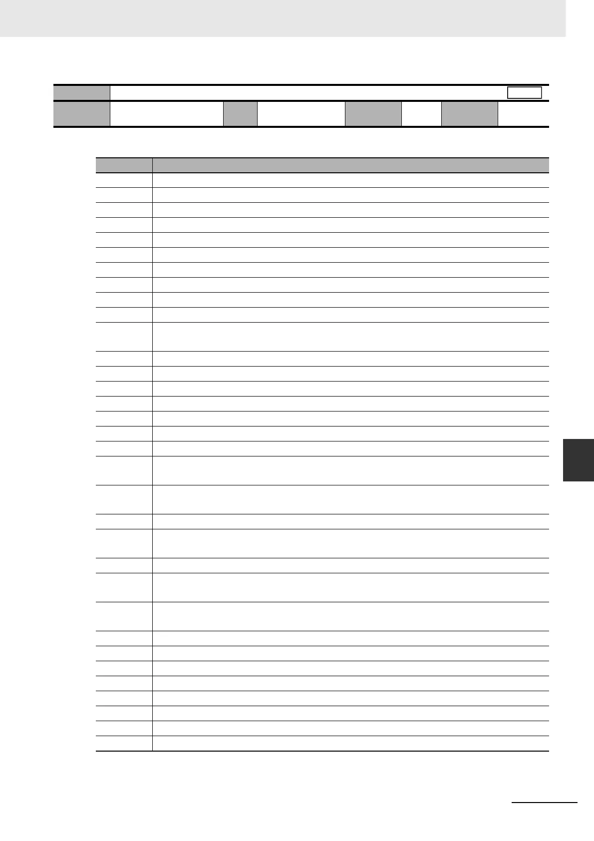
• Select the type of data to be displayed by default on the 7-segment front panel display when the
power supply is powered on.
Pn528
Default Display
Setting
range
0 to 35 Unit – Default
setting
1
Cycle the
power supply
Required
Set value Description
0 Position command error
1 Motor speed
2 Position command speed
3 Speed control command
4 Torque command
5 Total encoder pulses
6 Total command pulses
8 Reserved (Do not set.)
9 Control mode
10 I/O signal status
11 Reserved
(Do not set.)
12 Alarm factor, history
13 Warning number
14 Regeneration resistance load ratio
15 Overload load ratio
16 Inertia ratio
17 Reason for no rotation
18 Display of the number of I/O signal changes
20 Reserved
(Do not set.)
21 Reserved
(Do not set.)
22 Monitor for the number of encoder communications errors
23 Reserved
(Do not set.)
24 Position error (for each encoder)
25 Reserved
(Do not set.)
26 Reserved
(Do not set.)
27 P-N voltage
28 Software version
29 Drive serial number
30 Motor serial number
31 Accumulative operation time
32 Automatic motor recognition function
33 Temperature information
35 Reserved (Do not set.)
All

 Loading...


