EasyManua.ls Logo

Omron G5 Series User Manual

Omron G5 Series
506 pages
To Next Page IconTo Next Page
To Previous Page IconTo Previous Page
Page #388 background imageLoading...
Page #388 background image
7 Parameter Details
7 - 54
OMNUC G5-series (Pulse-train Input Type) AC Servomotors and Servo Drives User’s Manual
For details about the display, refer to 8-4 Mode Setting on page 8-6.
Do not set.
Set the maximum command pulse input value. A Command Pulse Frequency Error (Alarm No. 27.0)
occurs if the command pulse input frequency exceeds this value x 1.2.
The Servo Drive detects the Command Pulse Frequency Error for pulses it has accepted. Therefore,
if may not detect the error if the number of input pulses is much larger than the value set in this
parameter. In addition, setting the value to 1,000 or less enables the use of the digital filter for the
command pulse input as shown in the table below.
Explanation of Set Values
Set whether to enable or disable the detection of the Pulse Regeneration Error (Alarm No. 28.0).
Explanation of Set Values
Set whether or not to restrict operations on the front panel.
The restricted operation varies depending on the mode as shown in the table below.
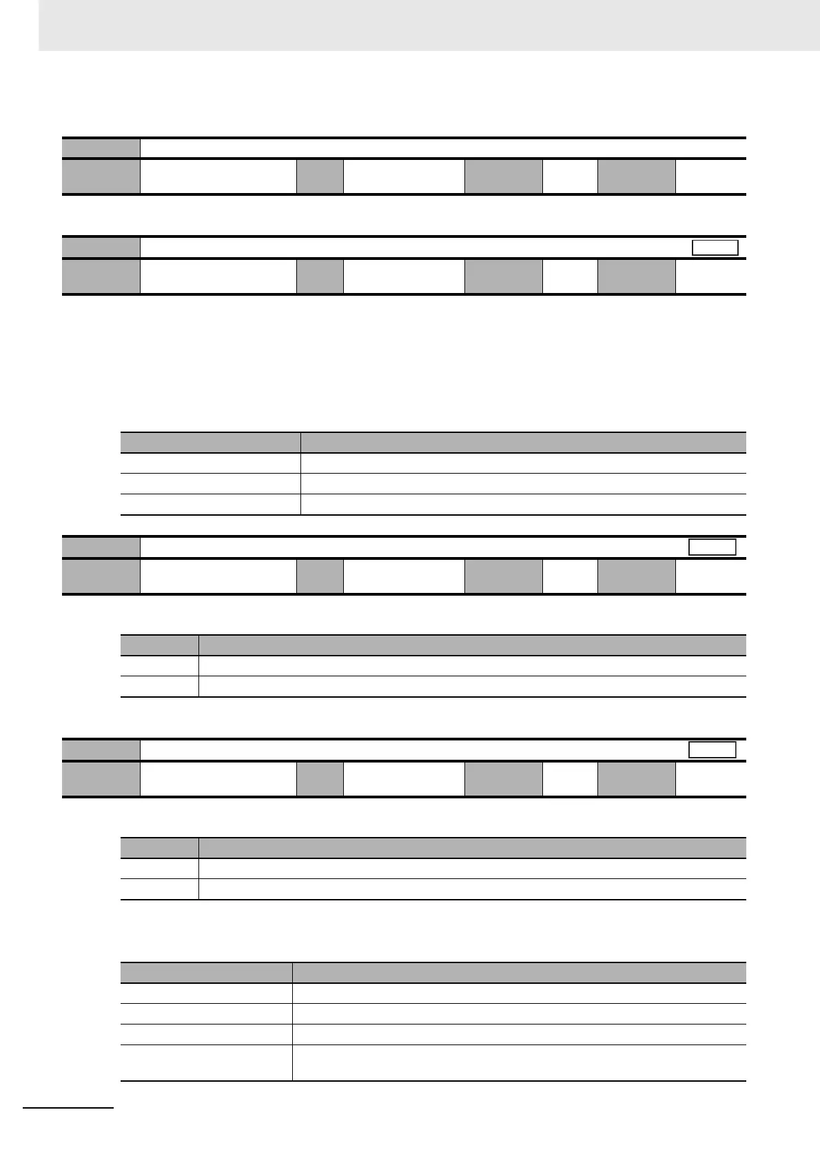
Pn531 Reserved
Setting
range
1 Unit Default
setting
1
Cycle the
power supply
Pn532
Command Pulse Input Maximum Setting
Setting
range
250 to 4,000 Unit Kpps Default
setting
4,000
Cycle the
power supply
Required
Pn532 set value Digital filter
250 to 499 200 ns × 2 readings
500 to 999 100 ns × 2 readings
1,000 to 4,000 None (through)
Pn533
Pulse Regeneration Output Limit Setting
Setting
range
0 to 1 Unit Default
setting
0
Cycle the
power supply
Required
Set value Description
0 Error detection disabled
1 Error detection enabled
Pn535
Front Key Protection Setting
Setting
range
0 to 1 Unit Default
setting
0
Cycle the
power supply
Required
Set value Description
0 Front panel operation not restricted
1 Front panel operation restricted
Mode Operations restricted
Monitor Mode All monitor data can be viewed.
Parameter Setting Mode Parameters cannot be changed. However, set parameter values can be viewed.
EEPROM Write Mode Unavailable (Not displayed)
Ancillary Function Mode Operations other than disabling the front key protection setting are unavailable
(not displayed).
Position
All
All

Table of Contents

Other manuals for Omron G5 Series

Questions and Answers:

Omron G5 Series Specifications

General IconGeneral
FeedbackIncremental Encoder, Absolute Encoder
CommunicationEtherCAT
Safety FunctionSTO (Safe Torque Off)
Protection FunctionsOvervoltage, Undervoltage, Overcurrent
Vibration Resistance4.9 m/s² (10 to 55 Hz)

Summary

AC Servomotors/Servo Drives G5-series

Read and Understand this Manual

Warranty and Limitations of Liability

Details OMRON's product warranty, limitations of liability, and disclaimers regarding product use and damages.

Application Considerations

Suitability for Use

OMR ON's disclaimer on product conformity to standards and suitability for specific applications.

Safety Precautions

Explanation of Displays

Explains the meaning of DANGER and Caution displays for hazardous situations.

Explanation of Symbols

Defines symbols used for danger, prohibition, and compulsory actions.

Installation and Wiring

Operation and Adjustment

Manual Configuration

Section 1 Features and System Configuration

Section 2 Models and External Dimensions

Section 3 Specifications

3-1 Servo Drive Specifications

Details general specifications, characteristics, and international standards for Servo Drives.

3-3 Servomotor Specifications

Lists general specifications, characteristics, and international standards for Servomotors.

System Design

4-1 Installation Conditions

Guidelines for installing Servo Drives, Servomotors, and Decelerators, covering space, environment, and mounting.

4-2 Wiring

Explains peripheral equipment connection examples and main circuit/motor connections.

4-3 Wiring Conforming to EMC Directives

Details requirements for wiring to ensure EMC Directive conformance, including noise reduction measures.

Basic Control Mode

5-1 Position Control

Explains the outline of position control, parameters, related functions, and block diagrams.

5-2 Internally Set Speed Control

Details the outline of internally set speed control, required parameters, and operation examples.

Applied Functions

6-6 Brake Interlock

Explains the brake interlock function for controlling the holding brake timing and operation.

Section 7 Parameter Details

7-1 Basic Parameters

Details fundamental parameters like rotation direction, control mode, realtime autotuning, inertia ratio, and command pulse settings.

7-2 Gain Parameters

Covers parameters for adjusting position loop gain, speed loop gain, and their integral time constants for optimal servo system performance.

Section 8 Operation

8-1 Operational Procedure

Outlines the sequence of steps for correct installation, wiring, function settings, trial operation, and adjustment.

8-2 Preparing for Operation

Lists essential items to check before turning ON the power supply, including voltage, wiring, and connections.

8-5 Trial Operation

Details inspections and procedures for performing trial operation to confirm servo system functionality.

Section 9 Adjustment Functions

9-1 Gain Adjustment

Explains the purpose and methods of gain adjustment, including realtime autotuning and manual tuning.

9-2 Realtime Autotuning

Describes the realtime autotuning process for estimating load inertia and automatically setting gain, including conditions for proper operation.

Section 10 Troubleshooting and Maintenance

10-1 Actions for Problems

Outlines preliminary checks and analytical methods to determine the cause of problems and take appropriate measures.

10-3 Alarm List

Details alarm codes, error detection functions, descriptions, causes, and measures for troubleshooting.

10-4 Troubleshooting

Guides on diagnosing errors based on alarm displays and operation states, providing probable causes and measures.

Appendices

Related product manuals