6 Applied Functions
6 - 10
OMNUC G5-series (Pulse-train Input Type) AC Servomotors and Servo Drives User’s Manual
Width Setting
This is the ratio of the frequency bandwidth at a damping factor of –3 [dB] relative to the center
frequency when the depth is 0. This value should conform to the left column in the table below.
Depth Setting
This is the I/O ratio at which the center frequency input is completely cut off at a set value of 0 and
completely passed at a set value of 100. If the indication unit is [dB], this value should conform to the
right column in the table below.
Notch Filter Width and Depth
Width Depth
Set value
Bandwidth/
center frequency
Set value I/O ratio [%]
Damping
factor [dB]
0 0.50 0 0 (Cut off) –
∞
1 0.59 1 1 –40.0
2 0.71 2 2 –34.0
3 0.84 3 3 –30.5
4 1.00 4 4 –28.0
5 1.19 5 5 –26.0
6 1.41 10 10 –20.0
7 1.68 15 15 –16.5
8 2.00 20 20 –14.0
9 2.38 25 25 –12.0
10 2.83 30 30 –10.5
11 3.36 35 35 –9.1
12 4.00 40 40 –8.0
13 4.76 45 45 –6.9
14 5.66 50 50 –6.0
15 6.73 60 60 –4.4
16 8.00 70 70 –3.1
17 9.51 80 80 –1.9
18 11.31 90 90 –0.9
19 13.45 100 100 (Passed) 0.0
20 16.00
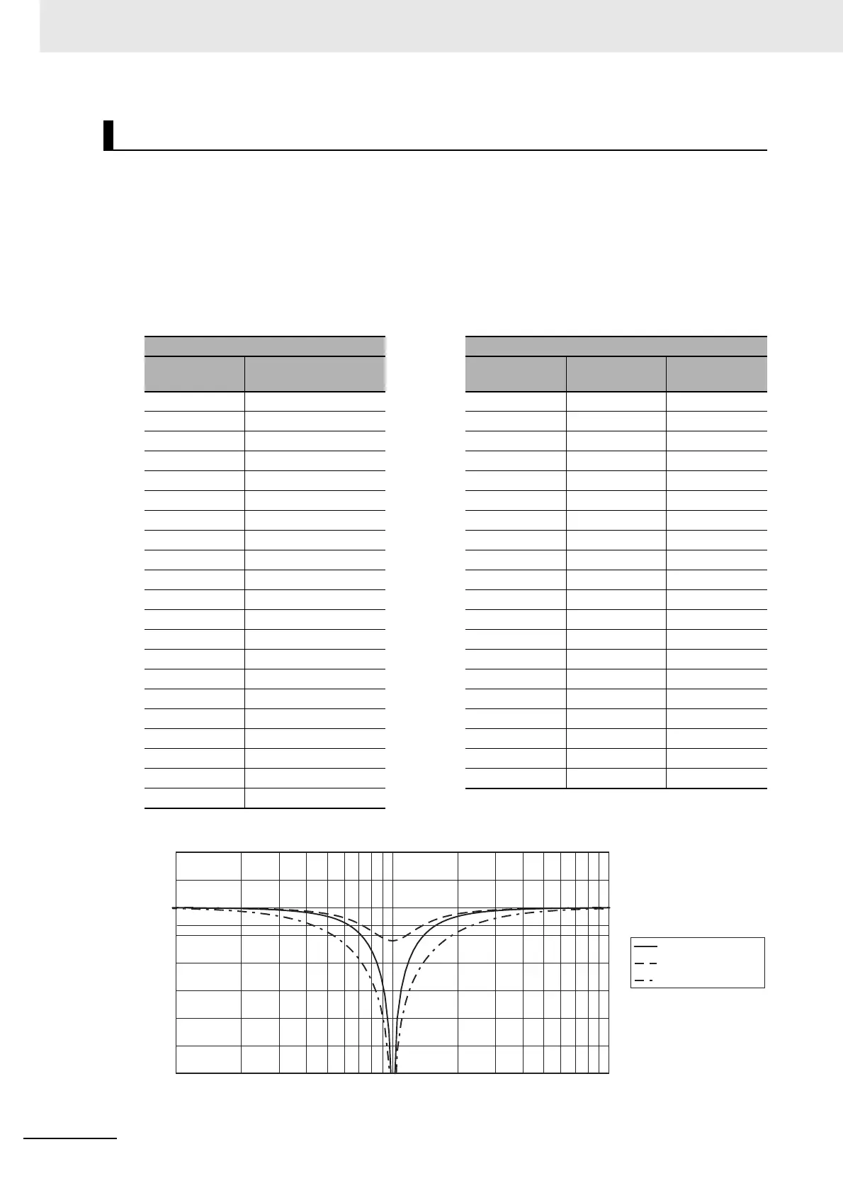
Notch filter frequency characteristics
-30
-25
-20
-15
-10
-5
0
5
10
000100101
Frequency [Hz]
Gain [dB]
-3[dB]
Depth 0, width 4
Depth 50, width 4
Depth 0, width 8

 Loading...


