R 20 mm
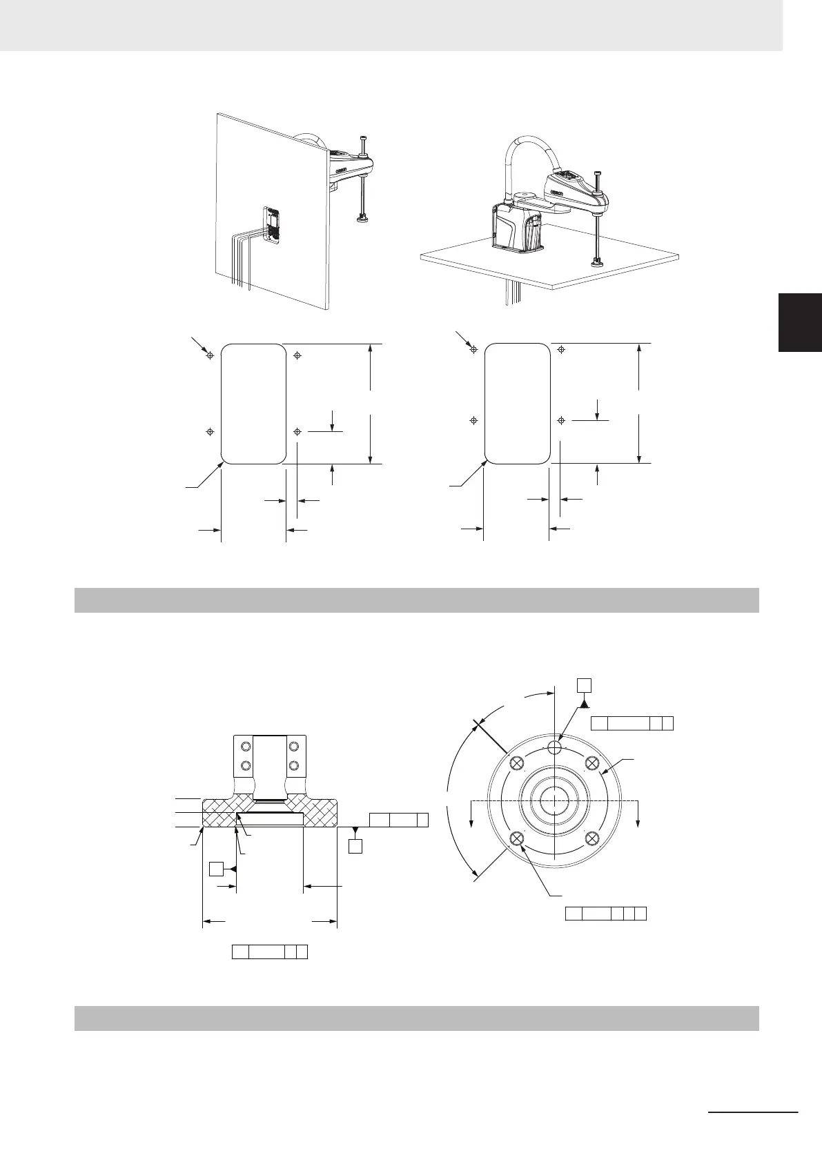
Mounting
Holes (x4)
20 mm
120 mm
59 mm
220 mm
R 20 mm
Top
Mounting
Holes (x4)
Front
Mounting
Holes (x4)
Mounting
Holes (x4)
120 mm
20 mm
79 mm
220 mm
2-1-3
Tool Flange Dimensions
The robot's tool flange dimensions are provided below. Geometry and tolerances meet
ISO-9409-1-50-4-M6 (2004) requirements for manipulating industrial robots.
b 0.02 B
1 mm x 45°
Ø 31.5 mm
+0.025
0
H7
Ø 63 mm
0
-0.046
H8
r
n 0.02 A B
Ø 6 mm
+0.015
0
THRU
j
n 0.040 A B
4 X Ø 5.5 mm THRU
M6 x 1.0 6H THRU
j
n 0.2 A B C
Ø 50 mm
A
C
SECTION A-A
SCALE 1:1
13 mm
6.8 mm
0
1 mm x 45°
A
B
R 0.3 mm
45°
90°
A
2-1-4
Front Panel Dimensions
The Front Panel dimensions are provided below.
2 Specifications
2-5
i4L Robots User's Manual (I658)
2-1 Physical Specifications
2
2-1-3 Tool Flange Dimensions
 Loading...


