Joint Hardstop
Position
Joint Limita-
tion
Range of Motion Software Limit Setting
i4-350L i4-450L i4-550L / i4-550L (350 mm Z)
1 Joint 1 -109.5°
2 +109.5°
3 Joint 2 -124° -118°
4 +124° +118°
5
See note
*1
-133°
6 +133°
7 Joint 3 5 mm from end of travel.
*1. The i4-350L model includes pre-installed hardstop screws in positions 5 and 6 to prevent base interference
with the quill. Do not remove these pre-installed hardstop screws.
3-5-1
Joint 1 Adjustable Hardstops
Use the following information when making joint 1 hardstop adjustments.
• Joint 1 hardstops require user-supplied M8 X 10 socket head cap screws, class 12.9.
• Apply Loctite thread lock type 243 or equivalent.
• Apply a torque of 17 N-m when tightening the hardstop screws.
3-5-2
Joint 2 Adjustable Hardstops
Use the following information when making joint 2 hardstop adjustments.
• Joint 2 hardstops require user-supplied M8 X 10 socket head cap screws, class 12.9.
• Apply Loctite thread lock type 243 or equivalent.
• Apply a torque of 17 N-m when tightening the hardstop screws.
3-5-3
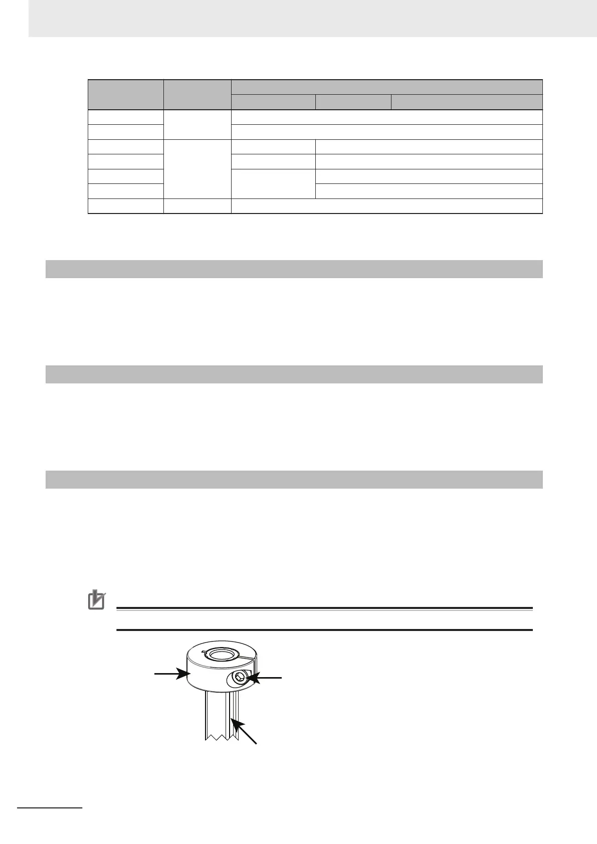
Joint 3 Adjustable Hardstop
The joint 3 down stroke can be limited by sliding the clamp collar down the z-axis quill to a lower posi-
tion.
The following tools are required when adjusting the joint 3 hardstop.
• 4 mm hex bit
• Torque wrench
• Loctite thread lock type 243 or equivalent
•
Precautions for Correct Use
Never loosen or remove the quill clamp collar while the z-axis brake is released.
Clamp Collar
Socket-head
Screw
Z-axis Quill
(Top End)
3 Installation
3-8
i4L Robots User's Manual (I658)

 Loading...


