3-9
Supplying Power and Ground
The robot requires separate 24 VDC and 48 VDC power supplies. The 24 VDC supply provides Con-
trol Power and the 48 VDC supply provides power to the internal servo amplifiers.
A lockout tagout main disconnect device must be installed on the AC supply to the 24 VDC and 48
VDC power supplies. These devices are user-supplied. Disconnect devices shall be accessible and
conveniently located to facilitate application of lockout devices during service and maintenance.
Use the information below to make all power supply connections to the robot.
Additional Information
Refer to 2-3-1 Power Supply Specifications on page 2-12 for information about power supply
requirements and other wiring details.
3-9-1
Grounding the System
The system should be grounded properly to avoid transient voltages or other electrical noise. There
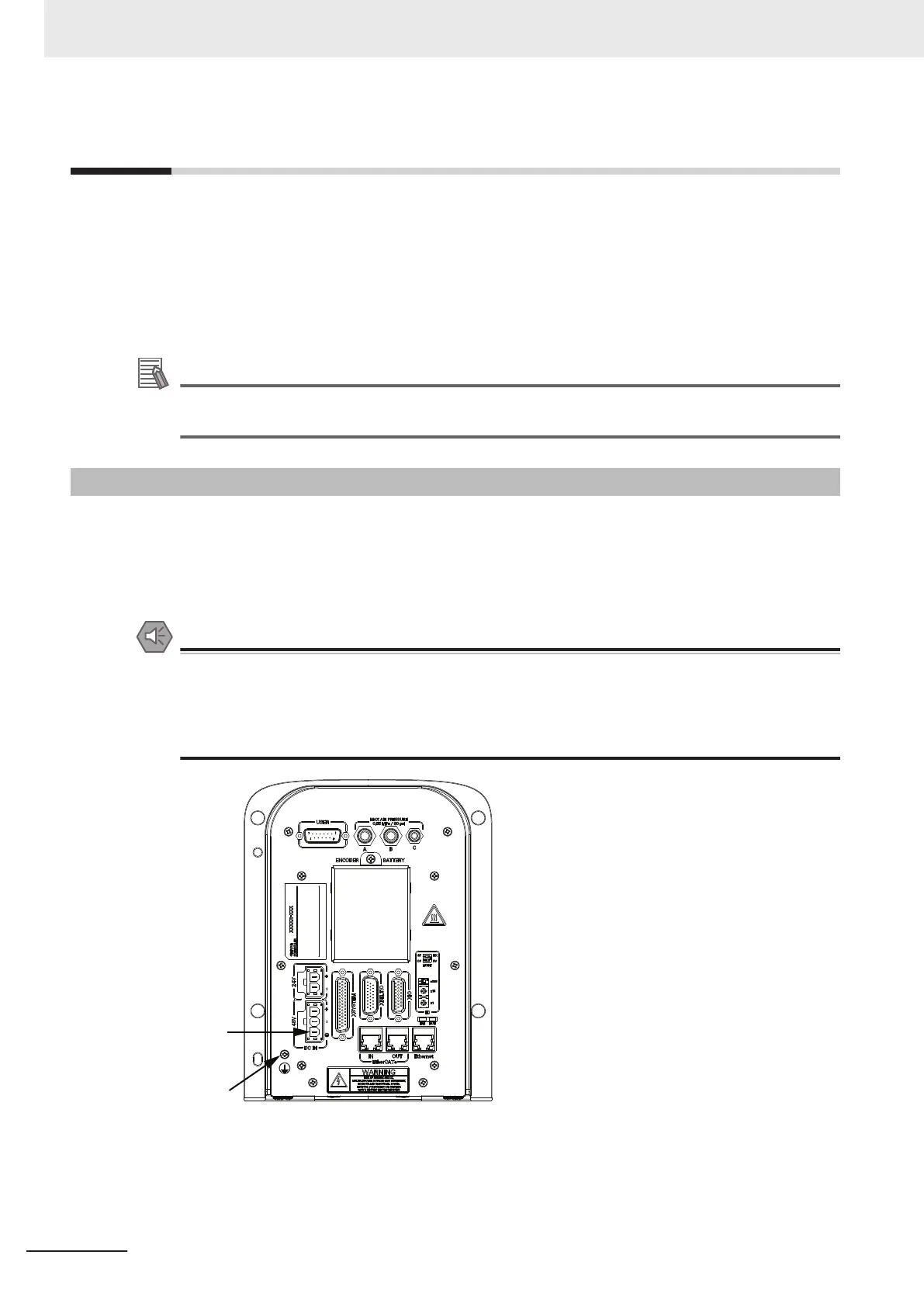
are two primary ground points on the system as described below.
• High Power ground
• Chassis ground
Precautions for Safe Use
The Joint 3 quill and the tool flange are not grounded to protective earth. If hazardous voltages
are present at any user-supplied robot-mounted equipment or tooling, you must install a ground
connection from that equipment or tooling to the ground point on the robot base.
Refer to 3-9-1 Grounding the System on page 3-28 for more information about grounding the
Tool Flange.
High Power
Ground
Chassis
Ground
3 Installation
3-28
i4L Robots User's Manual (I658)

 Loading...


