3-7
Connecting Digital I/O
The following sections describe the various methods to connect digital I/O to the robot.
3-7-1
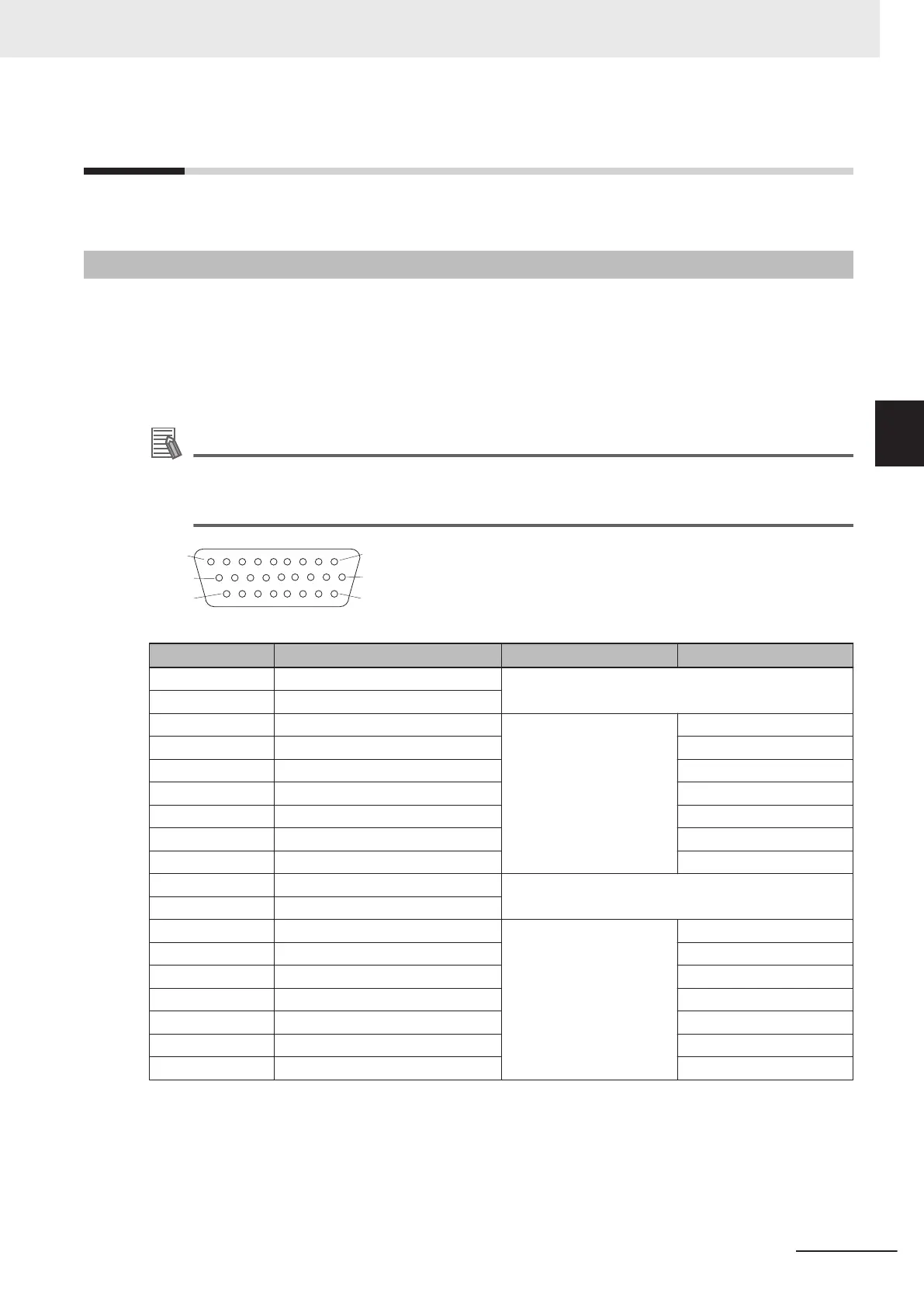
XIO Connector Signals and Wiring
The XIO connector on the Primary Interface Panel provides access to built-in digital I/O.
The 12 available inputs correspond to V+ signal numbers 1097 to 1108.
The 8 available outputs correspond to V+ signal numbers 0097 to 0104.
The XIO connector pin assignments are provided below. The Designation and Signal Bank information
in the table below only apply when using an XIO Termination Block.
Additional Information
Refer to 2-3-2 XIO and TIO Connector I/O Specifications on page 2-12 for electrical specifica-
tions. Refer to 2-5-1 Connector and Port Specifications on page 2-15 for connector specifica-
tions.
PIN 9
PIN 18
PIN 26
PIN 1
PIN 10
PIN 19
Pin Number Designation Signal Bank V+ Signal Number
1 Ground --
2 24 VDC
3 Common 1 1 --
4 Input 1.1 1097
5 Input 2.1 1098
6 Input 3.1 1099
7 Input 4.1 1100
8 Input 5.1 1101
9 Input 6.1 1102
10 Ground --
11 24 VDC
12 Common 2 2 --
13 Input 1.2 1103
14 Input 2.2 1104
15 Input 3.2 1105
16 Input 4.2 1106
17 Input 5.2 1107
18 Input 6.2 1108
3 Installation
3-13
i4L Robots User's Manual (I658)
3-7 Connecting Digital I/O
3
3-7-1 XIO Connector Signals and Wiring

 Loading...


