Pin Number Designation Signal Bank V+ Signal Number
19 Output 1 -- --
20 Output 2 0097
21 Output 3 0098
22 Output 4 0099
23 Output 5 0100
24 Output 6 0102
25 Output 7 0103
26 Output 8 0104
XIO Internal Circuits
Use the following information to understand the XIO internal circuits.
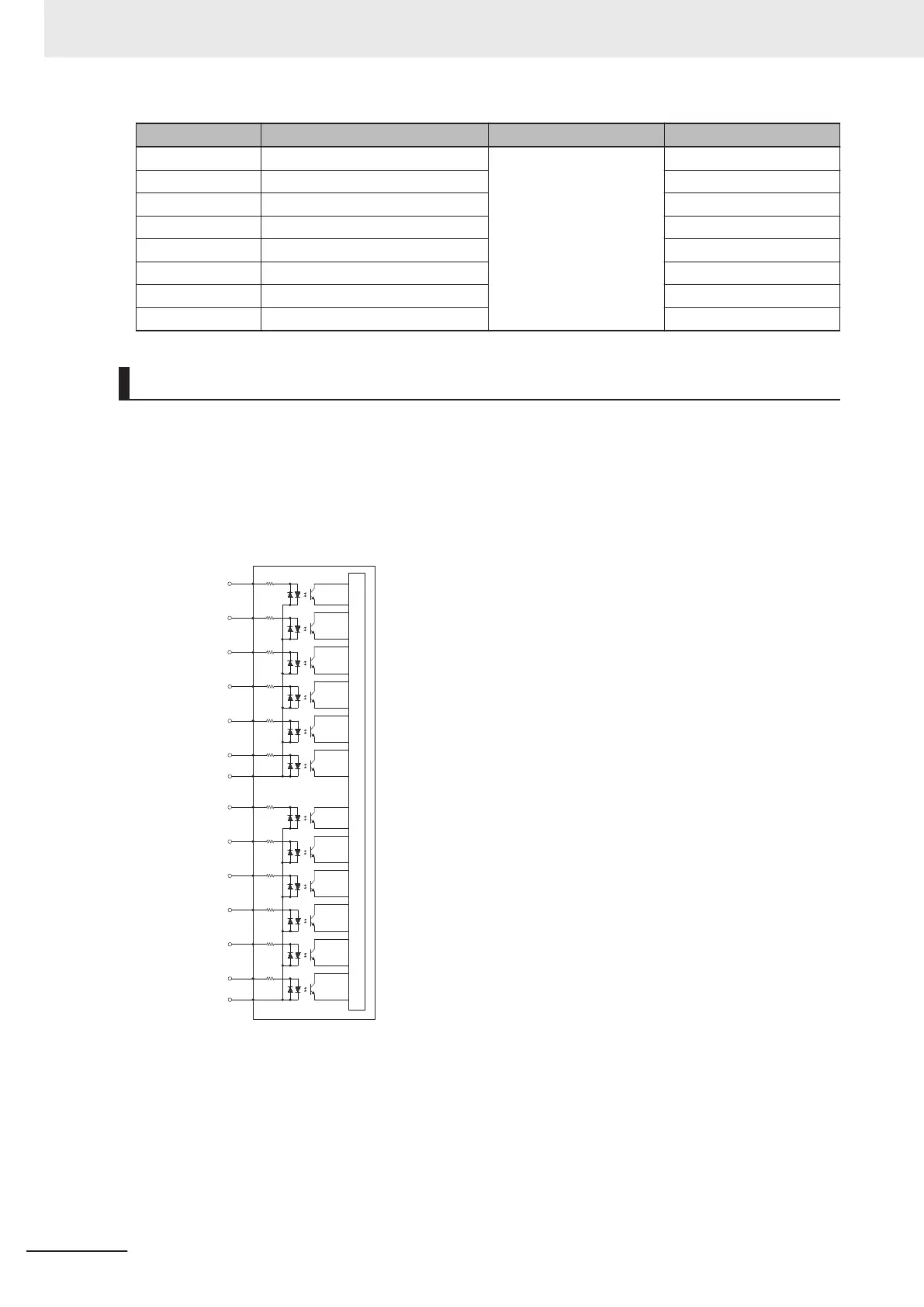
XIO Input Signals
The twelve inputs are arranged in two banks of six. Each bank is electrically isolated from the other
bank. Each input is optically isolated. The six inputs within each bank share a common source /
sink line.
Internal Circuits
Input 1.1
Input 1.2
Input 1.3
Input 1.4
Input 1.5
Input 1.6
Common 1
Common 2
Input 2.1
Input 2.2
Input 2.3
Input 2.4
Input 2.5
Input 2.6
XIO Output Signals
The eight outputs share a common, sourcing driver integrated circuit. The driver is designed to sup-
ply a load with one side connected to ground. Each channel is capable of switching up to 0.7 A of
current. This driver has over-temperature protection, shorted load protection, and is current limiting.
The driver draws power from the 24 VDC Control Power supplied to the robot through a self-reset-
ting polyfuse.
3 Installation
3-14
i4L Robots User's Manual (I658)

 Loading...


