Precautions for Safe Use
Output 8 can be assigned to indicate the robot's High Power state. When High Power is ena-
bled, this output will turn ON. When High Power is not enabled, this output will be OFF. This is
not a safety-rated means of indicating a High Power state and should only be used for monitor-
ing the robot status. Use the ACE software to make this configuration if needed.
Precautions for Correct Use
Use surge suppression when switching inductive loads such as relays to prevent damage to the
output circuits.
Additional Information
If there is an output short or other over-current situation, the affected output of the driver inte-
grated circuit turns OFF and back ON automatically to reduce the internal temperature.
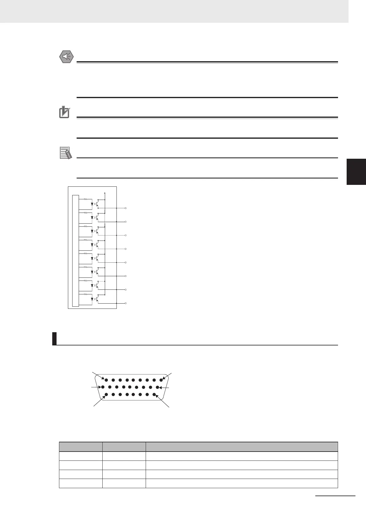
Internal Circuits
Output 1
+24 VDC
Output 2
Output 3
Output 4
Output 5
Output 6
Output 7
Output 8
XIO Breakout Cable Pinouts
Use the following diagrams for XIO Breakout cable pinout information.
PIN 9
PIN 18
PIN 26
PIN 1
PIN 10
PIN 19
Pin Number Signal Wire Color
1 GND White
2 24 VDC White / Black
3 Common 1 Red
4 Input 1.1 Red / Black
3 Installation
3-15
i4L Robots User's Manual (I658)
3-7 Connecting Digital I/O
3
3-7-1 XIO Connector Signals and Wiring

 Loading...


