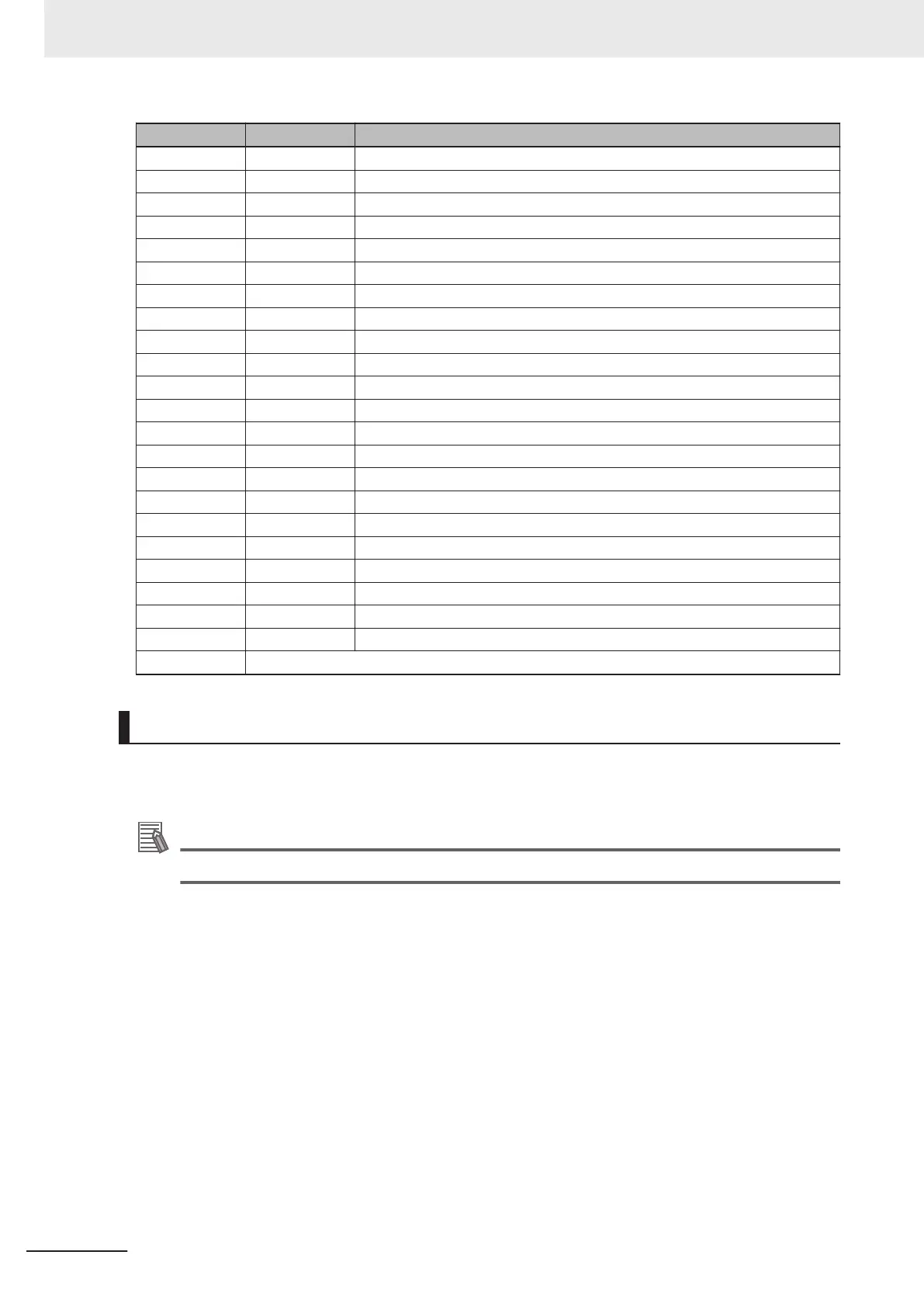
Pin Number Signal Wire Color
5 Input 2.1 Yellow
6 Input 3.1 Yellow / Black
7 Input 4.1 Green
8 Input 5.1 Green / Black
9 Input 6.1 Blue
10 GND Blue / White
11 24 VDC Brown
12 Common 2 Brown / White
13 Input 1.2 Orange
14 Input 2.2 Orange / Black
15 Input 3.2 Gray
16 Input 4.2 Gray / Black
17 Input 5.2 Violet
18 Input 6.2 Violet / White
19 Output 1 Pink
20 Output 2 Pink / Black
21 Output 3 Light blue
22 Output 4 Light blue / Black
23 Output 5 Light green
24 Output 6 Light green / Black
25 Output 7 White / Red
26 Output 8 White / Blue
Shell Shield
XIO Termination Block
An XIO termination block can be connected directly to the XIO connector to provide simple wiring and
access to the built-in I/O.
Additional Information
Refer to the Omron Adept IO Blox User's Guide (04638-000) for more information.
3 Installation
3-16
i4L Robots User's Manual (I658)

 Loading...


