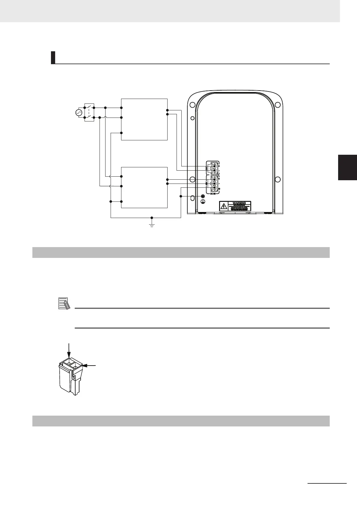
Ground Circuit
Use the following diagram to understand the recommended grounding circuit.
48 VDC
Power Supply
+
-
+
-
24 VDC
Power Supply
AC
Supply
Ground
Ground
L
N
L
N
Robot
Main
Disconnect
Device
3-9-2
24 VDC Connections
The 24 VDC Control Power connector is located on the Primary Interface Panel. A 24 VDC power sup-
ply mating connector is provided with the robot.
Use the illustration below to understand the polarity of the mating connector.
Additional Information
The connector and pins are provided with the robot and require assembly with user-supplied
wires. The connector part number is 02708-000. The pin part number is 02709-000.
3-9-3
48 VDC Connections
The 48 VDC High Power connector is located on the Primary Interface Panel. A 48 VDC power supply
mating connector is provided with the robot.
Use the illustration below to understand the polarity and ground terminals of the mating connector.
3 Installation
3-29
i4L Robots User's Manual (I658)
3-9 Supplying Power and Ground
3
3-9-2 24 VDC Connections

 Loading...


