3-7-2
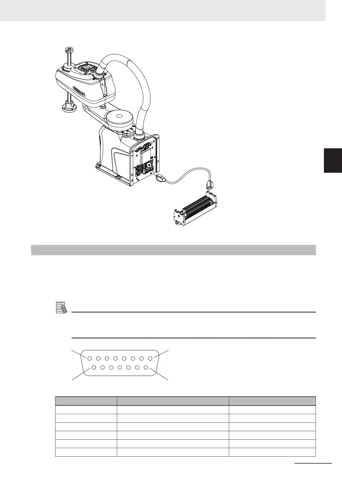
TIO Connector Signals and Wiring
The TIO connector on the Secondary Interface Panel provides access to built-in digital I/O.
The 5 available inputs correspond to V+ signal numbers 1033 to 1037.
The 4 available outputs correspond to V+ signal numbers 33 to 36.
The TIO connector pin assignments are provided below.
Additional Information
Refer to 2-3-2 XIO and TIO Connector I/O Specifications on page 2-12 for electrical specifica-
tions.
Refer to 2-5-1 Connector and Port Specifications on page 2-15 for connector specifications.
Pin Number Designation V+ Signal Number
1 Common –-
2 Input 5 1037
3 Input 2 1034
4 Input 4 1036
5 24 VDC –-
6 Output 3 35
3 Installation
3-17
i4L Robots User's Manual (I658)
3-7 Connecting Digital I/O
3
3-7-2 TIO Connector Signals and Wiring

 Loading...


