5-84
5-16 User Parameters
5
Operating Functions
Explanation of Settings
• The use of this parameter depends on the control mode.
• Use this parameter to set the relation between the voltage applied to the torque command input
(TREF1: CN1 pin 14 or TREF2: CN1 pin 16) and the Servomotor’s output torque.
• Refer to 5-4 Torque Control on page 5-8 for information on torque command scaling.
Explanation of Settings
• Use this parameter to reverse the polarity of the Torque Command Input (REF/TREF1: CN1 pin
14 or PCL/TREF2: CN1 pin 16).
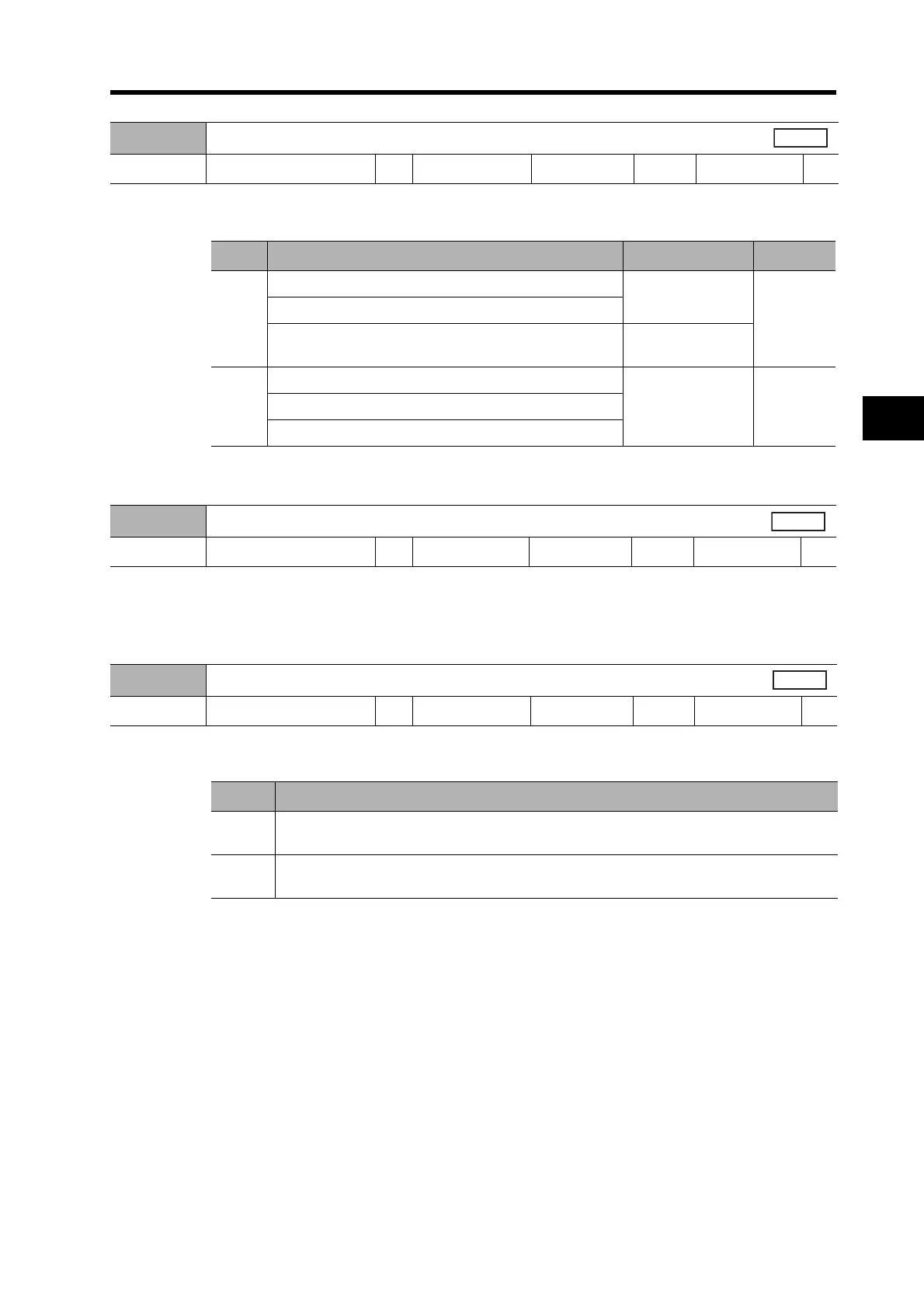
Pn5B
Torque Command/Speed Limit Selection
Setting range 0 or 1 Unit --- Default setting 0
Power OFF→ON
---
Setting Control mode Torque command Speed limit
0
Torque control
TREF1
(CN1 pin 14)
Pn5b
Torque control in Position Control/Torque Control Mode
Torque control in Speed Control/Torque Control Mode
TREF2
(CN1 pin 16)
1
Torque control
TREF2
(CN1 pin 16)
VLIM (CN1
pin 14)
Torque control in Position Control/Torque Control Mode
Torque control in Speed Control/Torque Control Mode
Pn5C
Torque Command Scale
Setting range 10 to 100 Unit 0.1 V/100% Default setting 30
Power OFF→ON
---
Pn5D
Torque Output Direction Switch
Setting range 0 or 1 Unit --- Default setting 0
Power OFF→ON
---
Setting Explanation
0
Direction of motor torque:
Clockwise (forward) for positive commands when viewing the end of the shaft
1
Direction of motor torque:
Counterclockwise (reverse) for positive commands when viewing the end of the shaft
 Loading...


