EasyManua.ls Logo

Omron ZFX-C User Manual

Omron ZFX-C
236 pages
To Next Page IconTo Next Page
To Previous Page IconTo Previous Page
Page #120 background imageLoading...
Page #120 background image
Additional Functions
ZFX-C User’s Manual
3
SETTING THE MEASUREMENT CONDITIONS
117
Trigonometric functions
Geometrical functions
Logic functions
Function Description
SIN Calculates the sine. The result is returned in the range -1 to 1.
Specify the angle in the numerical expression in degrees.
SIN (numerical expression)
COS Calculates the cosine. The result is returned in the range -1 to 1.
Specify the angle in the numerical expression in degrees.
COS (numerical expression)
ATAN Calculates the arc tangent of the Y-axis and X-axis components.
The result is returned as a radian in the range -π to π.
ATAN (Y-axis component, X-axis component)
Example: To calculate the angle formed between a horizontal line and a straight line join-
ing the gravities of items 0 and 1
ATAN (I001.Y-I000.Y, I001.X-I000.X)
When both of the two arguments are 0, 0 is returned as the calculation result to indicate
that the judgment is NG.
Function Description
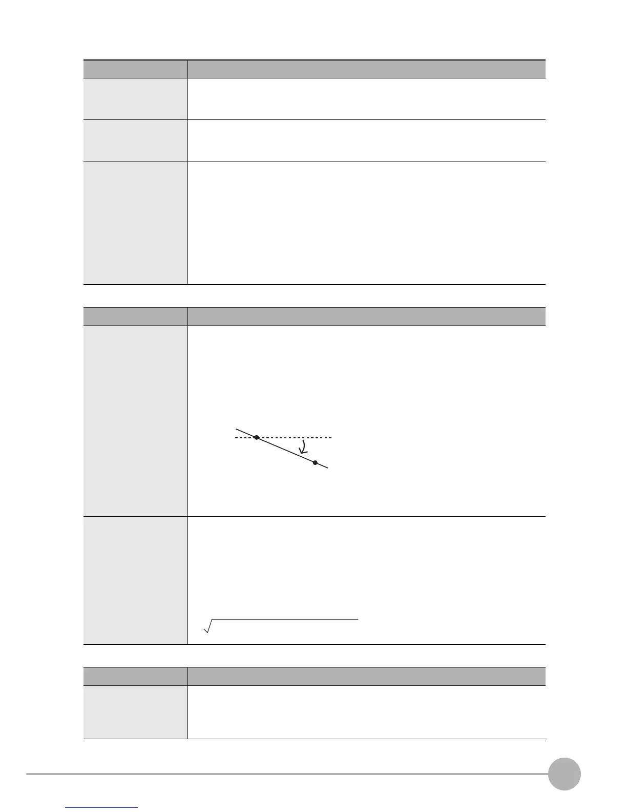
ANGL Calculates the angle formed by a straight line connecting two points (gravity and center of
model).
The angle is calculated with respect to the horizontal line. The result is returned in the
range -180 to 180.
ANGL (Y-axis component, X-axis component)
Example: To calculate the angle formed by a straight line joining the gravities of items 0
and 1
ANGL (I001.Y-I000.Y, I001.X-I000.X)
When both of the two arguments are 0, 0 is returned as the calculation result to indicate
that the judgment is NG.
DIST Calculates the distance between two points (gravity and center of model).
DIST (X-axis coordinate of 1st point, Y-axis coordinate of 1st point, X-axis coordinate of
2nd point, Y-axis coordinate of 2nd point)
Example: To calculate the distance between the gravities of items 0 and 1
DIST (I000.X, I000.Y, I001.X, I001.Y)
The following calculation is performed internally:
Function Description
AND Calculates the logical product.
When either of the arguments is "0", "0" is returned as the calculation result, and "-1" is
returned for the other argument.
AND (argument1, argument 2)
(horizontal line)
2nd point
1st point
(I001.X-I000.X)
2
+ (I001.Y-I000.Y)
2

Table of Contents

Other manuals for Omron ZFX-C

Questions and Answers:

Omron ZFX-C Specifications

General IconGeneral
BrandOmron
ModelZFX-C
CategoryAccessories
LanguageEnglish

Summary

User's Manual

Application Considerations

Safety and usage guidelines before operating the product.

Before Use

Essential steps and information required before starting product operation.

Basic Operations

Covers fundamental procedures for using the ZFX-C vision sensor.

Setting the Measurement Conditions

Guides users on configuring measurement parameters and settings.

Precautions for Safe Use

Precautions for Correct Use

1. BEFORE USE

System Configuration

Details the basic setup and components of the ZFX-C system.

Part Names and Functions

Identifies and describes the main components and their functions.

Mounting and Connecting Devices

Instructions for physically installing and connecting the ZFX-C hardware.

2. BASIC OPERATIONS

Inspection Setup and Measurement

Step-by-step guide for setting up inspections and performing measurements.

Troubleshooting

Solutions for common problems encountered during operation.

3. SETTING THE MEASUREMENT CONDITIONS

Setting Measurement Items

Describes how to select and configure specific measurement types.

Cameras/Lighting

Configuration settings for camera and lighting to optimize image capture.

4. FUNCTIONS USED DURING OPERATION

Monitoring the Measurement Status - RUN Mode

How to view real-time measurement status and results.

Checking/Adjusting the Measurement - ADJ Mode

Procedures for checking and fine-tuning measurement parameters.

5. ADDITIONAL FUNCTIONS

Bank Settings

Manages multiple sets of configurations (banks) for different applications.

System Settings

Configuration of system-level parameters like communication and display.

6. PARALLEL INTERFACE

Connection

Instructions for establishing physical connections using the parallel interface.

Signal I/O

Details on input and output signals for parallel communication.

Part Names and Functions

Cameras

Details specific to the camera units, including their types and features.

Controller

Mounting and Connecting Devices

Installing Cameras

Specific steps for mounting the camera units.

Installing the Controller

Connecting Devices

Connecting the Controller to the Power Supply

Steps for connecting the controller unit to its power source.

Overview of Settings and Measurement

Operation Modes

Explanation of the different operational modes (MENU, ADJ, RUN).

Measurement Items and Banks

Initializing Controller Settings

Saving Setup Data

Inspection Setup and Measurement

Setting Measurement Conditions - MENU Mode

Detailed configuration of measurement parameters via the MENU mode.

Troubleshooting

Clear Images Cannot be Obtained

Troubleshooting steps for when images are not acquired correctly.

Measurement Target Cannot be Measured Accurately Due to Movement

Solutions for measurement inaccuracies caused by target movement.

Setting Measurement Items

Shape Inspection

Inspects based on object shape and form.

Size Inspection

Measures dimensions like area, width, and position.

Edge Inspection

Detects edges based on brightness changes.

Bright/Color Inspection

Measures brightness, hue, and saturation of colors.

Defect

Detects imperfections like scratches or burrs.

Image Adjustment

Settings to improve image quality for better measurement.

Cameras/Lighting

Configuration of camera and lighting parameters.

Position Correction

Corrects measurement position based on detected target location.

Additional Functions

Advanced functionalities such as calculations and expressions.

Calculation

Performs mathematical operations on measurement data.

Threshold

Image adjustment (if necessary)

Detailed settings (if necessary)

Setting Measurement Items

Pattern Search

Locates known patterns within an image for identification.

Flexible Search

Sensitive Search

Size Inspection

Area

Measures the size of the detected color region.

Labeling

Edge Inspection

Position

Calculates the coordinates of detected edges.

Width

Count

Angle

Bright/Color Inspection

Bright

Measures the brightness level of the target.

HUE

Inspection by Individual Application

Grouping

Groups products based on their similarity to registered models.

Defect

Image Adjustment

Select Camera

Selects the camera to be used for image processing.

Color Filter

Applies color filters to enhance image contrast.

Color Pickup/Binary

Pre-processing

Background Suppression

Brightness Control

Cameras/Lighting

Shutter Speed

Adjusts shutter speed to match target movement and lighting.

Gain Setting

Adjusts sensor sensitivity for better image brightness.

Partial Function Settings

Image Rate

Light Control (Recipe Functions)

Calibration

Registering Images

Position Correction

Additional Functions

Calculation

Performs mathematical operations on measurement data.

Logging Monitor

Log Settings

Configures data logging parameters and warning triggers.

Display condition

Sets conditions for displaying data on the logging monitor graph.

FUNCTIONS USED DURING OPERATION

Monitoring the Measurement Status - RUN Mode

How to view real-time measurement status and results.

Checking/Adjusting the Measurement - ADJ Mode

Procedures for checking and fine-tuning measurement parameters.

Monitoring the Measurement Status - RUN Mode

Displaying Measurement Information

How to switch and view different types of measurement information.

Switching the Image Display Method

Using a Saved Image to Perform Re-measurement

Checking/Adjusting the Measurement - ADJ Mode

Checking Measurement Status

Verifies measurement accuracy and adjusts threshold values.

Adjusting Logging Monitor Conditions

Adjusting Measurement Conditions

Adjusting Measurement Item Conditions

Specific adjustments for individual measurement items.

ADDITIONAL FUNCTIONS

Bank Settings

Manages multiple sets of configurations (banks) for different applications.

Bank Data Operations

Operations for copying, renaming, or erasing bank data.

Bank Group Operations

Manages groups of banks, especially when using an SD card.

System Settings

Camera Specifications

Sets basic camera conditions for the connected controller.

Communication Setup

Configures communication parameters for external devices.

Communication Setup

Normal

Settings for serial communication in normal mode.

Parallel Communication

Configuration for parallel communication protocols.

ENABLE reverse

Ethernet Communication

Output Settings

Output Conditions

Binary format

Configures output of measurement values in binary format.

Display Settings

ECO Display

Enables a power-saving display mode by dimming the LCD.

Display Setting

Designate Colors

Changes text colors for OK/NG status and normal display.

Calculation List Settings

Customizes the display format of calculation results lists.

Operation Settings

Display Capture

Captures the LCD screen content and saves it as an image file.

Saving during Switching of Bank Groups

Password

Key Lock in RUN Mode

Measurement Control Conditions

Measurement Image Save Conditions

Sets conditions for saving measurement images.

Saved Image Delete Conditions

Sets conditions for clearing saved images.

Handling the ENABLE Signal

Operation when the TRIG signal is input during measurement

Operation Conditions during Startup

Setting/Changing the Display Language

Setting/Changing the Date

Clearing Saved Images

Tools

Saving/Loading Data

Backs up and restores setup and image data using SD cards.

SD Card Operations

Checking Density Distribution (Profile)

Checking the Communication Status with External Devices

Displaying the Controller Information

RS-232C/422 Communication

Monitor conditions

Parallel Communication

Error display items

PARALLEL INTERFACE

Connection

Instructions for establishing physical connections using the parallel interface.

Signal I/O

Details on input and output signals for parallel communication.

Timing Charts

Visual representation of signal timing for parallel communication.

Connection

Parallel I/O Connector 0 (Standard Parallel Port)

Wiring and connection details for the standard parallel port.

Parallel I/O Connector 1 (Extended Parallel Port)

Signal I/O

Input Signal

Describes input signals like TRIG, DI0-DI7, and their functions.

Command Input

Format and commands for controlling the device via digital inputs.

Internal Specifications

Input Specifications

Electrical characteristics of input signals.

Output Specifications

Signal I/O

Commands

List of commands that can be input via DI0-DI7 for controlling the device.

Output Signal

Judgment Result Output

Overall judgment result

Sets conditions for the overall judgment output signal.

Individual judgment result

Configures output of individual judgment results for expressions.

Measurement Value Output

Timing Charts

Measurement (Handshaking OFF)

Timing diagram for measurements without synchronization.

Continuous Measurement

Timing Charts

Signal Operation in terms of Measurement

Details signal operations during measurement processes.

ENABLE Signal Output

OR Signal Output

Operation at Startup

Error Messages and Corrective Actions

List of Available Functions for Each Camera

AUTO Setting

AUTO Setting of Measurement Items

Guides the process of automatically setting measurement items.

AUTO Setting in Individual Adjustment Screens

AUTO Setting of Lighting

Specifications and External Dimensions

Camera

Detailed specifications for various camera models.

Specifications and External Dimensions

ZFX-SC10/SC50/SC50W/SC90/SC90W/SC150/SC150R/SC150W (color type)

Specifications for the color camera series.

Specifications and External Dimensions

ZFX-SR10R/SR50R (monochrome type)

Specifications for monochrome cameras.

Specifications and External Dimensions

Camera only

Specifications for cameras that do not include built-in lighting.

Controller

Specifications

Detailed technical specifications of the controller.

External Dimensions

Specifications and External Dimensions

ZFX-SC150/SC150R/SC150W (color type)

Specifications for the ZFX-SC150 series color cameras.

Accessories & Options

Camera Cable

Details about the cables used for connecting cameras.

Right Angle Camera Cable

Camera Extension Cable

Camera Long-distance Extension Cable

Parallel I/O Cable

RS-232C/422 Cable

LCD Monitor

Console

Panel Mount Adapters

Optional Lighting

ZFV-LTL01 (bar lighting)

Specifications for the bar lighting unit.

ZFV-LTL02 (bar double-lighting)

Specifications for the bar double-lighting unit.

ZFV-LTL04 (bar low-angle lighting)

ZFV-LTF01 (light source for through-beam lighting)

LED Safety

Classification

Details on laser product class classifications and standards.

Warning Label

Information about warning labels affixed to the product.

Requirements from Regulations and Standards

Summary of Requirements to Manufactures

Overview of safety requirements for manufacturers.

Summary of Requirements to User

Basic Knowledge for Operation

Input Methods

Describes how to interact with the device using touch pen, keys, or console.

Parameter Setup

Setting numerical values

Instructions for inputting numerical values using the on-screen keyboard.

Setting the Region

Moving and resizing regions

How to adjust the position and size of measurement regions.

Combining multiple shapes

Techniques for creating complex regions by combining basic shapes.

How Color Images are Processed

Color Filter

AUTO

Select Filter

Manually selecting a color filter from a palette.

Fixing the Color Filter

Disables automatic color filter updates to maintain a fixed setting.

Color Pickup

Fine-adjusting colors

Hue, Saturation and Brightness Value

Version Upgrade Information

Revision History

Related product manuals