Tools
154
ZFX-C User’s Manual
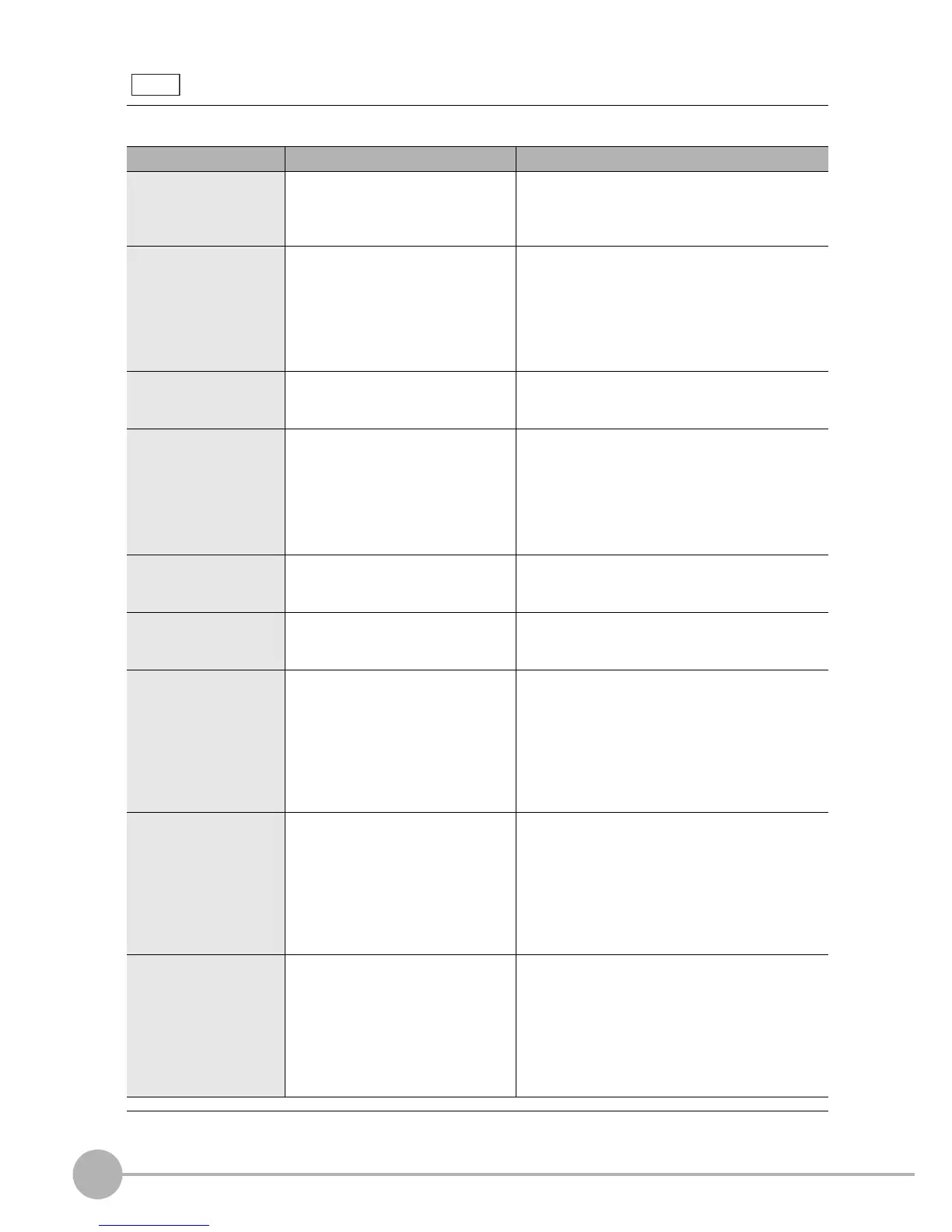
Error display items
The error display items displayed at [Error history] are as follows:
When an error is displayed, perform the appropriate remedy according to the indicated remedy.
Display Item Cause Remedy
Trigger input The trigger signal acceptance error
occurred since the trigger was input
when the ENABLE signal was OFF.
When using a PLC, change the PLC ladder program
so that triggers can be input when the ENABLE sig-
nal is ON. If the ladder program is normal, check to
see if the trigger signal is causing chattering.
Parallel command The command error occurred since
the parallel command confirmation
signal (DI8) was input when the
ENABLE signal was OFF, or the
specified command (DI7 to DI5) was
an undefined signal state.
When using a PLC, change the PLC ladder program so
that the DI8 signal can be input when the ENABLE sig-
nal is ON. If the ladder program is normal, check to see
if the DI8 signal is causing chattering.
Also, check to see if the DI7 to DI5 signals are at the sig-
nal level of the command to be executed, and applied
before the DI8 signal is input.
SD CARD access A write error occurred since the
measurement result could not be
output correctly to the SD card.
Check the following:
• Make sure that the CD card is inserted properly.
• Make sure that the SD card is not locked.
Parallel timeout A time-out error occurred since the
time to process the following events
exceeded the fixed time (default: 10
seconds) during handshaking.
• Measurement end
→
DSA signal ON
• GATE signal ON
→
DSA signal OFF
• GATE signal OFF
→
DSA signal ON
Check the ladder program to see if handshaking
has been correctly executed on the PLC.
USB connection
An output error occurred since the
measurement result could not be out-
put correctly via the USB interface.
Check to see if the USB cable is inserted correctly.
LAN connection An output error occurred since the
measurement result could not be
output correctly via the LAN.
Check to see if the LAN cable is inserted correctly.
Check to see if the LAN communication condition
is set correctly.
Image input The following caused a communica-
tion error between the camera and
Controller:
• Faulty connector contacts
• Broken cable leads
• Noise-induced data corruption
Check the camera cable to see if it is connected cor-
rectly between the camera and the Controller.
Replace the cable if its leads are broken.
If this does not remedy the problem, a probable
cause is that the communications error is occurring
due to noise buildup on the camera cable. Move the
camera and Controller away from noise-generating
sources.
VDIN timeout The following caused a communica-
tions error between the camera and
Controller:
• Faulty connector contacts
• Broken cable leads
• Noise-induced data corruption
Check the camera cable to see if it is connected cor-
rectly between the camera and the Controller.
Replace the cable if its leads are broken.
If this does not remedy the problem, a probable
cause is that the communications error is occurring
due to noise buildup on the camera cable. Move the
camera and Controller away from noise-generating
sources.
Camera
communication
The following caused a communica-
tion error between the camera and
Controller:
• Faulty connector contacts
• Broken cable leads
• Noise-induced data corruption
Check the camera cable to see if it is connected cor-
rectly between the camera and the Controller.
Replace the cable if its leads are broken.
If this does not remedy the problem, a probable
cause is that the communications error is occurring
due to noise buildup on the camera cable. Move the
camera and Controller away from noise-generating
sources.