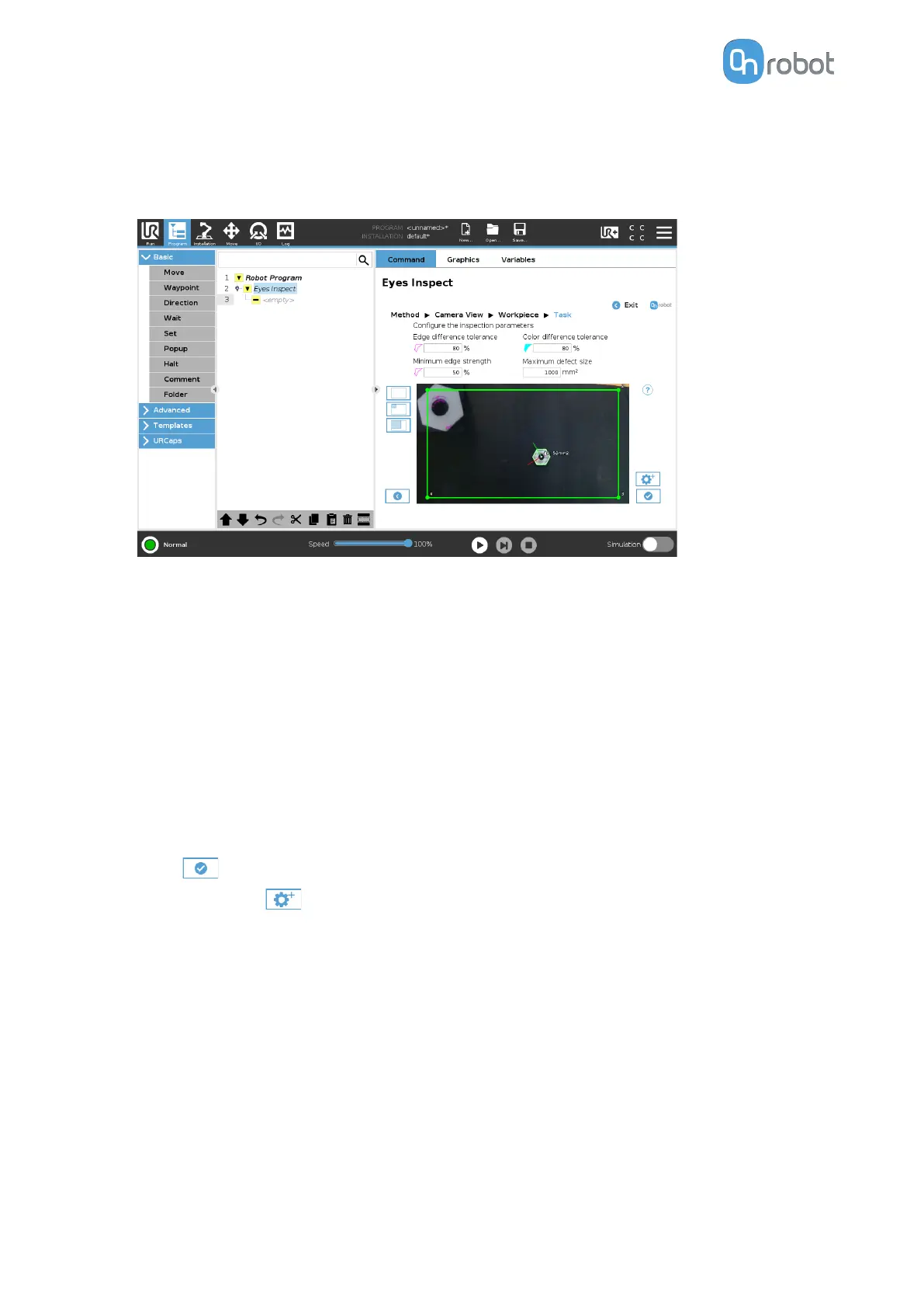
You can adjust the region of interest, which is marked by a yellow rectangle in the image.
To change the region of interest, adjust the corners by clicking and dragging each of the
points to its new position. The green region moves first, then the yellow follows, indicating
that you successfully changed the region of interest.
•
Edge
dierence tolerance: Specifies how dierent in orientation the considered
edges can be for a specific edge point to be classified as correct. Edge orientation is
defined as the direction in which the color changes (creating the edge).
•
Color
dierence tolerance: Defines how much the color of the workpiece can vary for
a pixel to be considered as a defect. Setting the parameter to 100% means that the
color is not considered when the task inspects the object.
•
Minimum edge strength: Specifies how strong edges are considered when calculating
the Edge Dierence. The strength of an edge is related to the dierence of colors in
both sides of the edge. For example, a transition from black to white is a strong edge,
while transition from orange to red is a weaker edge.
•
Maximum defect size (mm2): Specifies how much area the defective pixels of the
workpiece may cover before the workpiece fails the inspection. Pixels are considered
defective based on the Edge
dierence tolerance and the Color dierence tolerance.
•
Press and go to Finish Configuration.
•
Optionally, press to go to the advanced settings.
•
Adjust the inspection by setting the Detection height min, Detection height max,
Background sensitivity, and Pixel
filter size parameters.
OPERATION
77


 To Next Page