MercuryiTC
©2014 Oxford Instruments Omicron NanoScience. All rights reserved.
Page 120
9.2.2 Basic check of board operation
1 Power up the MercuryiTC. If fitted correctly, the iTC will detect the board and may request
permission to use it.
2 Put the iTC in Local mode by tapping the local/remote toggle button on the iTC Home page.
3 Tap Settings, scroll to and tap the Devices tab.
4 Scroll down the list of devices and find the level meter board. Also, scroll to the right to read
the firmware version.
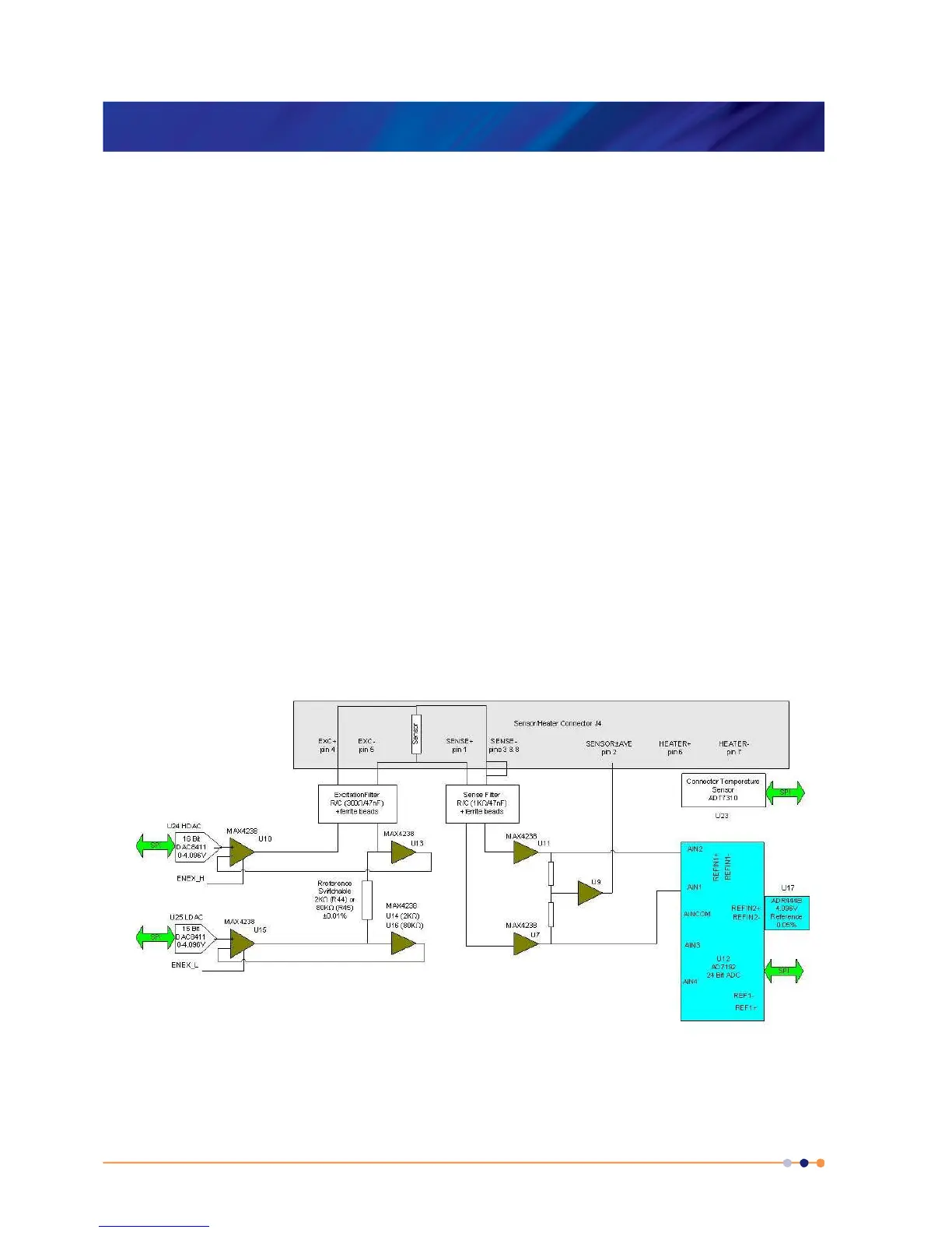
9.3 Circuit description of the temperature sensor
board
Depending on the sensor, the circuit can be configured to measure either resistance or voltage.
9.3.1 Voltage measurement mode
Voltage measurement mode is used with diode sensors or thermocouples. The following block
diagram summarises the principles.
If an excitation current is required, the sensor and a reference resistor (R44 or R45) are
connected in series. Digital to analogue converters (DACs) U24 and U25 generate an upper
 Loading...