MercuryiTC
©2014 Oxford Instruments Omicron NanoScience. All rights reserved.
Page 58
4.9.3 Changing a gas flow set point
1 Tap Control on the Home page. The Control loop configuration page is displayed.
2 Select the required temperature sensor in the Sensor field.
3 Tap the Flow(%) so that it displays Manual.
4 Enter the new gas-flow set point (as a percentage of maximum flow) in the Flow (%)
parameter box.
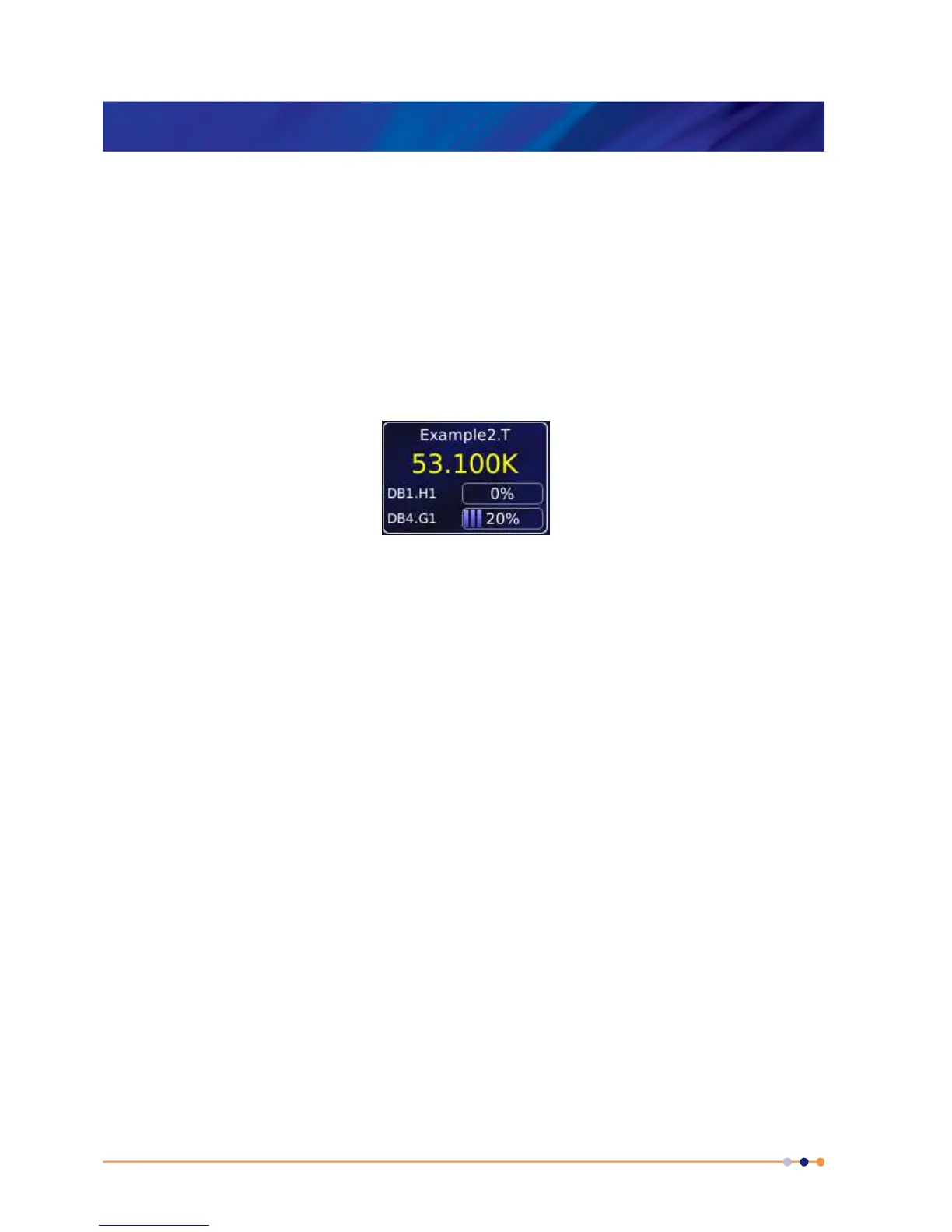
5 Tap Home to return to the Home page. The sensor widget will show the gas flow setting.
4.10 Using a generic calibration-file
4.10.1 Overview
Some generic calibration files are supplied for common sensors having reasonably predictable
forms of measured variable (e.g. resistance) as a function of temperature, for example sensors
that conform to the ITS-90 standard. However, the response of an individual sensor may
deviate slightly from the standard curve.
If two known temperatures are available, it is possible to make small adjustments to the scale
and offset of the standard curve to match a particular sensor. This process can be used for PTC
and NTC sensors.
The adjustment is applied to the measured variable, so for a resistance sensor the adjustment
is applied to the measured resistance.
For best results, the scaling adjustment should be applied at the high-value end of the measure
variable and the offset at the low-value end. So for a NTC resistance sensor, apply the scaling
at the known low-temperature point (ideally near the high-resistance end of the range). If a
scale adjustment of more than a few percent is required to correct the temperature reading,
investigate the measurement set-up to check there is not some other error present.
 Loading...