MercuryiTC
©2014 Oxford Instruments Omicron NanoScience. All rights reserved.
Page 14
2.1 MercuryiTC front and rear panels
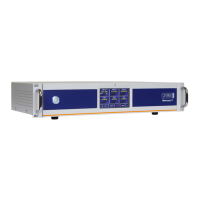
Figure 1 shows the front panel of the MercuryiTC and identifies the main features.
Figure 1 MercuryiTC front panel
The On/Off button on the front panel switches the iTC into/out of STANDBY mode. When the
switch is off, electrical power is still supplied to the switch-mode power supply inside the iTC.
The On/Off button illuminates blue when the iTC is powered up.
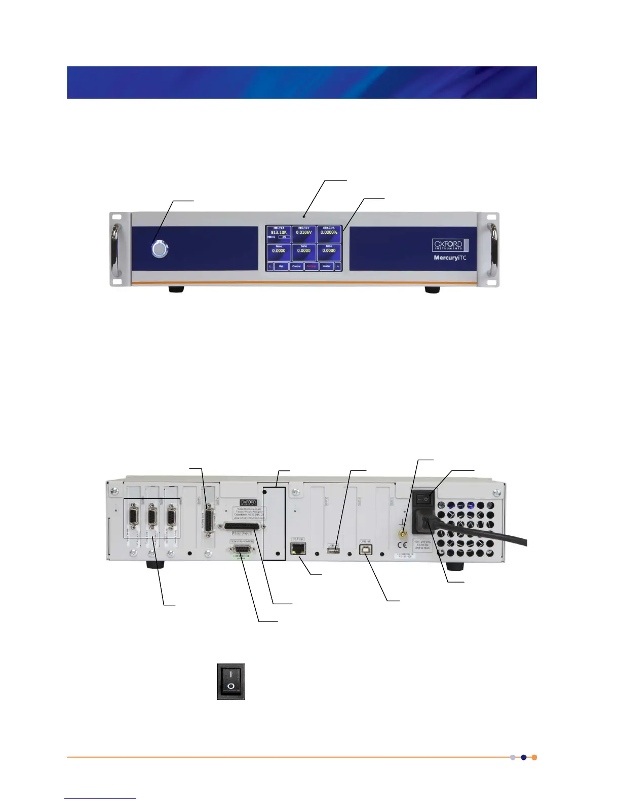
Figure 2 shows the rear panel of a MercuryiTC. This photo will not look exactly like your iTC as
it depends on the number and type of boards fitted.
Figure 2 MercuryiTC rear panel (example)
The switch on the rear panel turns electrical power on and off. All connectors are
labelled.
Additional
sensor/heater
connections
Auxiliary connection
RS232 / ISObus
Main heater/sensor
connection
TCP/IP
(Ethernet)
USB-A
USB-B
Functional ground
Mains inlet
Blank plate
 Loading...