IV–91
P13 Refrigerant Circuit Error (3WAY)
Error detection method
• The indoor unit outputs this warning when it determines that a compressor, outdoor solenoid valves, system
refrigerant should be inspected.
• For detailed inspection procedure, see P13 Refrigerant Circuit Fault (W MULTI).
• The system stops and there is no automatic reset when this warning is output.
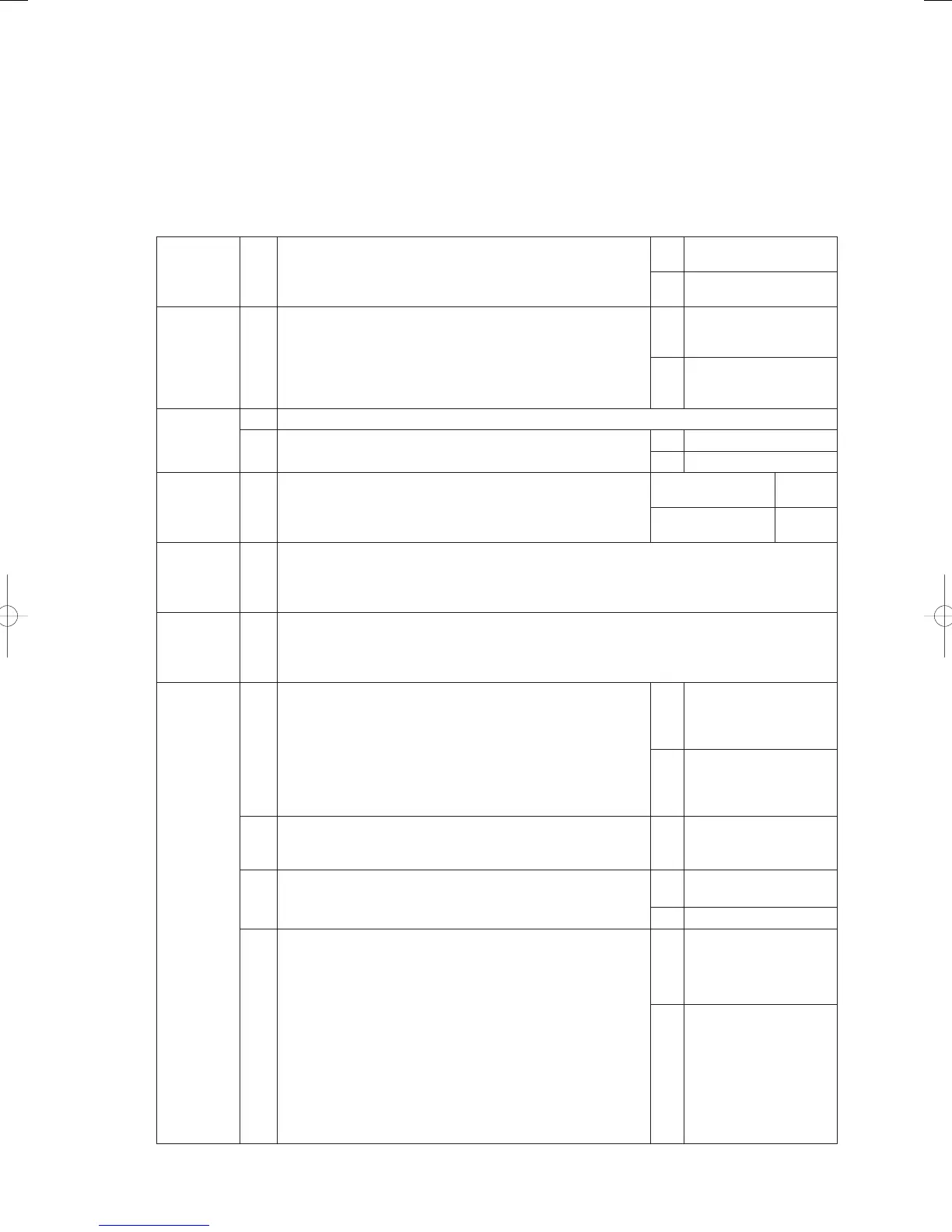
Troubleshooting
1
Pressure
sensor
inspection
1-1
For adjustment of the pressure sensor, see (adjustment
procedure section F16).
OK 2-1
NG Repair
2
Inspect
system
refrigerant
2-1
Use the No. 4 test mode “v_open” (valve open) to equalize the
pressure to assess whether amount of refrigerant is extremely
low when it is lower in pressure than saturated pressure
at ambient temperature. (Assessed as out of gas when
extremely low)
Out of refrigerant gas?
Yes
Check for refrigerant
leaks and repair.
No 3-1
3
Inspect the
compressor.
3-1 Turn off the outdoor unit (be sure to do this before work)
3-2
Use the instructions in P26 Clutch Connection Fault, to adjust
operation and wiring of clutch 1 and 2. Any problems?
Yes 4 -1
No 7-1
4
Inspect
refrigerant
oil.
4-1
Replace the compressor and check the refrigerant oil in the
replaced compressor for contamination.
Not contaminated 5-1
Contaminated 6-1
5
Replace
compressor
(1)
5-1
After replacing the compressor, perform a trial operation and check the equipment. Check
completed if OK.
6
Replace
compressor
(2)
6-1 Perform a fl ashing cleaning to clean the inside of the refrigerant tubes.
7
Inspect
outdoor
solenoid
valves
7-1
Adjust outdoor solenoid valves. Use trial operation mode
to check that the solenoid valves operate normally in
each operating mode (cooling/heating) and measure
tube temperature around solenoid valves to assess. (For
information on solenoid valve operation in each operating
mode, see the sections Control functions - Operating control
in the “Outdoor unit manual.”
Does the solenoid valve operate normally?
Yes
Replace outdoor main
board
No 7-2
7-2
Adjust the power board.
Does the power board CN013 output the solenoid power
supply voltage (AC 200V)?
Yes 7-3
7-3
Any poor connection and broken wires in wiring between the
power board and the relay board?
Yes Repair wiring
No 7-4
7-4
Adjust the outdoor main board.
In No. 4 test mode when “v_open” (valve open), is there a
drive output voltage (DC 12V) from discharge valves 1-1, 1-2,
discharge valve 2, suction valve 2-1 and 2-2?
(9P (white) CN018)
Discharge valve 1-1, 1-2: between No. 3 - 9 Discharge valve 2:
between No. 4-9
Suction valve 2-1, 2-2: between No. 6 - 9
Does suction valve 1 output a drive voltage (DC 12V) during
cooling operation?
Suction valve 1: between No. 3 - 9
* Note that suction valve 1 closes when powered (the other
valves operate in the opposite way)
Yes 7-5
No
Replace outdoor main
board
GHPtroubleshooting.indbIV‒91GHPtroubleshooting.indbIV‒91 2012/11/2611:20:142012/11/2611:20:14