IV–21
A21 Coolant Level Error
Error detection method
• A fl ag will be set if the possibility of air entering the coolant circuit is detected during air-mix confi rmation
operations prior to starting the engine (complete combustion.) (The engine will continue to operate.)
An error will be triggered if this possibility is detected three consecutive times.
* However, there are also cases in which the error will be triggered after only one detected when operating
after the [Automatic Air Purge Mode] ([S Air]) or when the engine is fi rst started after an A21 error has been
reset.
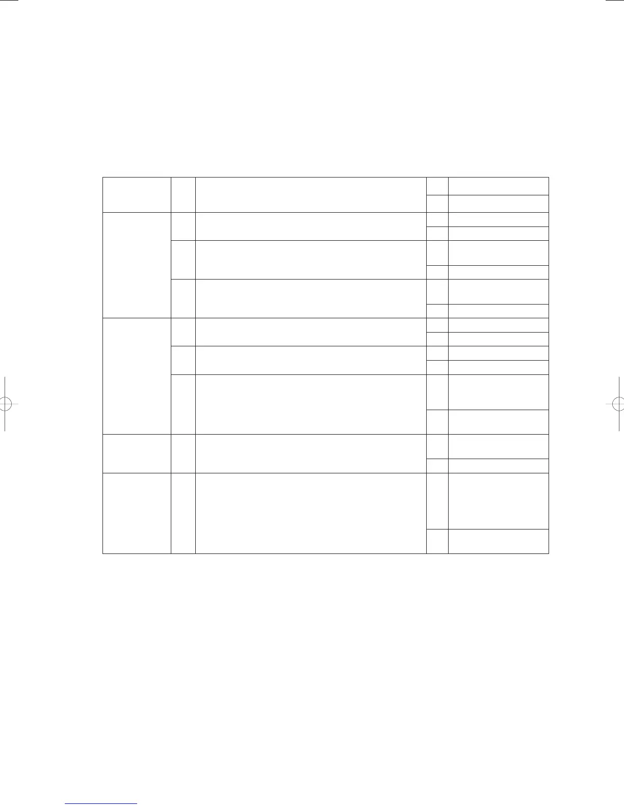
Troubleshooting
1
Coolant level
check
1-1 Is the prescribed amount of coolant in the reserve tank?
Yes 3 -1
No 2-1
2
Coolant leakage
check
2-1
Are there any external signs of coolant leaks? Check
visually.
Yes Repair
No 2-2
2-2 Can any coolant be confi rmed in the oil pan?
Yes
Replace the engine
head or packing
No 2-3
2-3
Remove the drain hose from the exhaust gas heat
exchanger and operate the pump. Is any coolant emitted
from the outlet?
Yes
Replace the exhaust gas
heat exchanger
No 3-1
3
Air-mix check
3-1 Can any air be confi rmed in the coolant circuit?
Yes 3 -2
No 4-1
3-2
Does air continue to be emitted no matter how many times
the air purging process is performed?
Yes 3 -3
No End after air purge
3-3
Does air continue to be emitted even after the engine has
been shut down?
Yes
Check for leaks on the
plate heat exchanger
and repair if necessary.
No
Replace the engine
head or packing
4
Coolant pump
check
4-1
Are there any severed wires, defective contacts or short
circuits on the coolant pump’s lock?
Yes
Replace the coolant
pump
No 5-1
5
Coolant electric
three-way valve
check
5-1 Is the coolant electric three-way valve operating normally?
Yes
If the problem reoccurs,
replace the outdoor unit’
s power board or main
board and keep an eye
on the situation.
No
Replace the three-way
coolant valve.
● For work procedure for replacing outdoor main board, see “5. Reference Document”.
● For board and Electrical Wiring Diagram, see Chapter 6.
• Outdoor main board: page VI-2
• Outdoor power board: page VI-3
• Converter board: VI-4
• Indoor control board for DC motor models: page VI-5
• Outdoor Unit Electrical Wiring Diagram: page VI-6
GHPtroubleshooting.indbIV‒21GHPtroubleshooting.indbIV‒21 2012/11/2611:20:072012/11/2611:20:07