VI–5
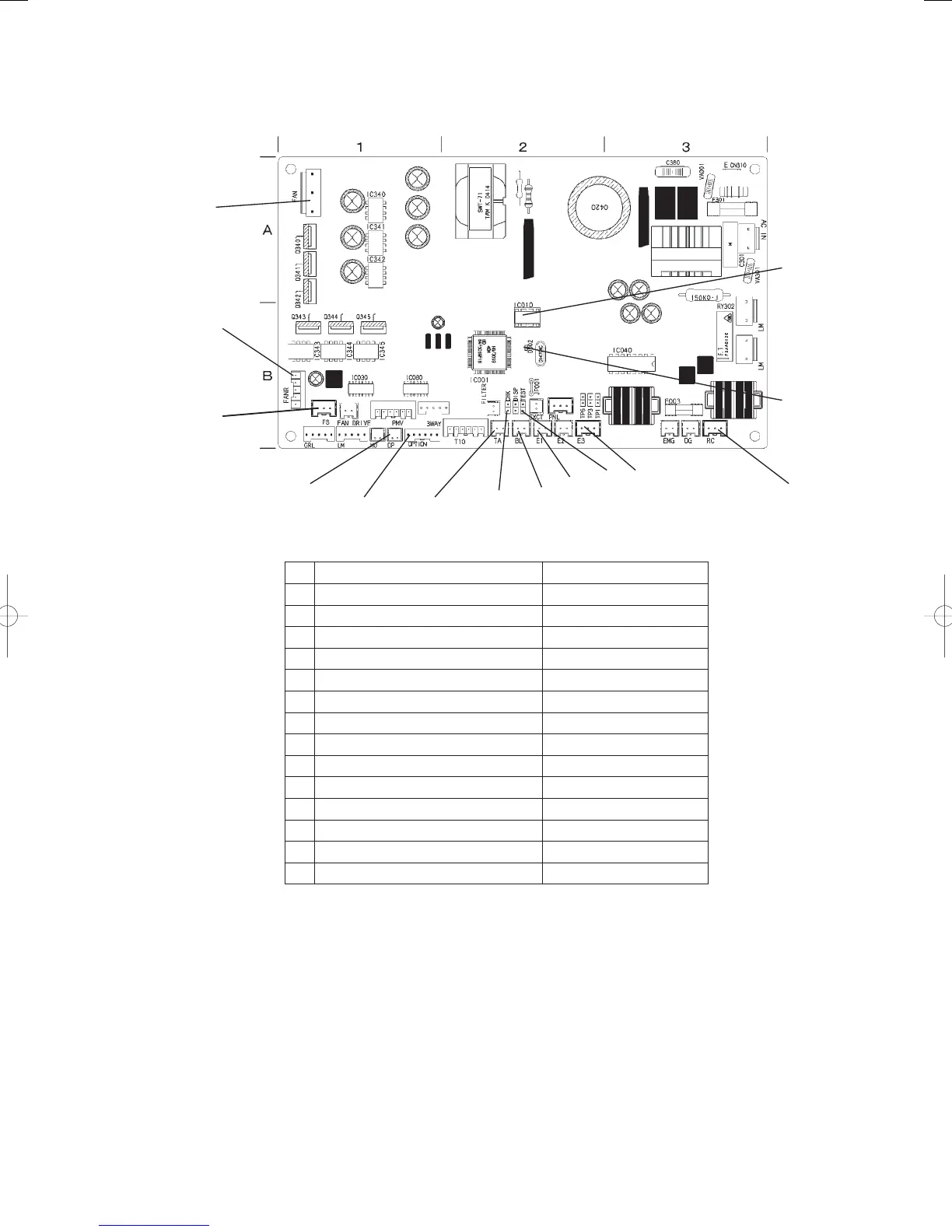
(4) Indoor control board for DC motor models
14
13
12
11
10
9
8
7
6
5
4
3
2
1
No. Name Position in the diagram
1 EEPROM B-2
2 LED B-2
3 RC B-3
4 Heat exchanger outlet E3 (brown) B-2
5 TEST pin (CN2) B-2
6 Heat exchanger inlet E1 (red) B-2
7 Discharge (green) (BL) B-2
8 CHK pin (CN5) B-2
9 Room temp (intake) TA (yellow) B-2
10 OPTION B-1
11 CN078 DP (red) B-1
12 CN034 FS (red) B-1
13 CN334 (red) B-1
14 CN333 (red) A-1
GHPtroubleshooting.indbVI‒5GHPtroubleshooting.indbVI‒5 2012/11/2611:20:322012/11/2611:20:32