VI–2
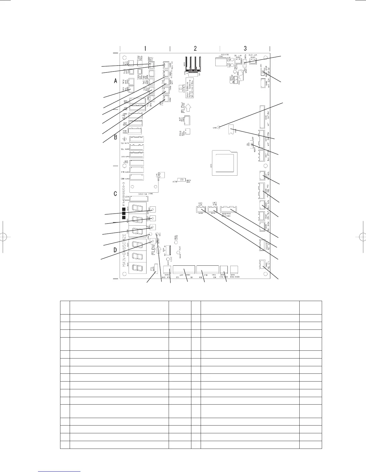
(1) Outdoor main board
1
2
3
18
4
19
20
21
22
23
11
12
1314
15
16
8
17
10
9
7
6
5
24
25
26
27
28
29
30
31
No. Name
Position in
the diagram
No. Name
Position in
the diagram
1 Terminal resistor ON/OFF switch (S010) A-3 17 CN075 D-1
2 STOP SW (S001) A-3 18 EEPROM B-3
3 Indoor/outdoor communications monitor (D043) B-2 19 CN037(WHITE) C-3
4 Gas solenoid valve forced off switch (S002) B-3 20
CN049(RED) Compressor outlet/inlet pressure
sensors. PS1: Inlet, PS2: outlet
C-3
5 SET key (S007) C-1 21 CN029(BLUE) C-3
6 DOWN key (S006) C-1 22 CN014(BLUE) C-3
7 UP key (S005) D-1 23 CN016(BLACK) C-2
8 LEVEL LED (D053) D-1 24 CN062(GREEN) Hot water outlet temperatur A-1
9 TEST/WARNING LED (D052) D-1 25 CN060(BLUE) Clutch coil temperature A-1
10 HOME key (S004) D-1 26 CN058(WHITE) Coolant temperature A-1
11 CN015(WHITE) C-2 27 CN059(BLACK) Outdoor air temperature A-1
12 CN063(YELLOW) D-3 28
CN055(BLUE) Heat exchanger inlet
temperature
A-1
13 CN012(RED) D-3 29 CN064(YELLOW) Clutch 2 coil temperature A-1
14 CN011(BLACK) D-2 30 CN053(BLACK) Compressor inlet temperature A-1
15 CN010(WHITE) D-2 31 CN054(RED) Compressor outlet temperature A-1
16 CN006(BLACK) D-1
GHPtroubleshooting.indbVI‒2GHPtroubleshooting.indbVI‒2 2012/11/2611:20:312012/11/2611:20:31