IV–2
(4) Troubleshooting
A01 Engine Oil Pressure Error
Error detection method
• When the engine oil pressure switch is OFF continuously for 4 seconds during engine operations (complete
combustion,) the engine will be shut down momentarily and an error fl ag set. The reason for the engine being
shut down is due to the error fl ag being triggered fi ve consecutive times in one hour.
* When the engine oil pressure switch is not detected within ten seconds of the engine being started (complete
combustion.)
• When oil pressure (engine earth common) K21 or K25 (short circuit) are detected at the engine oil pressure
switch contact with oil pressure detected.
Troubleshooting
1
Oil level
1-1 Is there oil in the storage side of the oil tank?
Yes 2-1
No 1-2
1-2 Any oil leaks or dirty oil?
Yes Repair
No 1-3
1-3 Is the tank side of the oil tank empty?
Yes Add oil
No 1-4
1-4 Does the oil fi ll pump operate properly?
Yes
Check for pinched
or clogged hose
No 1-5
1-5 Any oil fi ll pump wiring broken or disconnected?
Yes Repair wir ing
No Replace pump
2
Oil
pressure
switch
2-1
After engine operation (complete combustion), does the voltage
between the oil pressure switch terminal (+) and body ground (–)
measure DC 0V?
Yes 3 -1
No 2-2
2-2
At engine start, does the oil pressure measure 49kPa (0.5kg/cm
2
) or
more?
Yes
Oil pressure switch
defective
No 2-3
2-3 Is the oil fi lter clogged?
Yes Replace oil fi lter
No Engine is defective
3
Wiring
3-1
Does any of the wiring below contain broken wires or suffer from poor
connection, contact or crimping? • Wiring from outdoor main board
connector 2P (red) CN012 No. 1 to oil pressure • Wiring from outdoor
main board connector 2P (red) CN021 No. 1 to power board connector
2P (red) CN038 No. 1 Wiring between switches • Wiring from outdoor
main board connector FG CN075 to (-) terminal on starter power supply
Yes Repair wir ing
No
Replace outdoor
main board
● For work procedure for replacing outdoor main board, see “5. Reference Document”.
● For board and Electrical Wiring Diagram, see Chapter 6.
• Outdoor main board: page VI-2
• Outdoor power board: page VI-3
• Converter board: VI-4
• Indoor control board for DC motor models: page VI-5
• Outdoor Unit Electrical Wiring Diagram: page VI-6
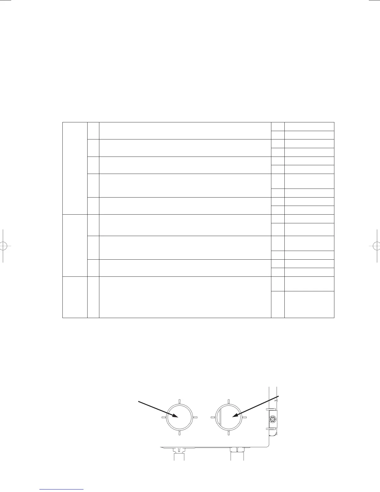
• 1-1
Storage side
Tank side
Oil tank, top view
GHPtroubleshooting.indbIV‒2GHPtroubleshooting.indbIV‒2 2012/11/2611:20:052012/11/2611:20:05