IV–17
A17 CT Error (Starter Current Detection Failure)
Error detection method
When the starter power primary current meets the following conditions, an error is determined upon 5
occurrences in 1 hour.
• During cranking: With no detection of starter current, and with revolution speed pulse detected, when 5
seconds pass during cranking or when engine attains complete combustion.
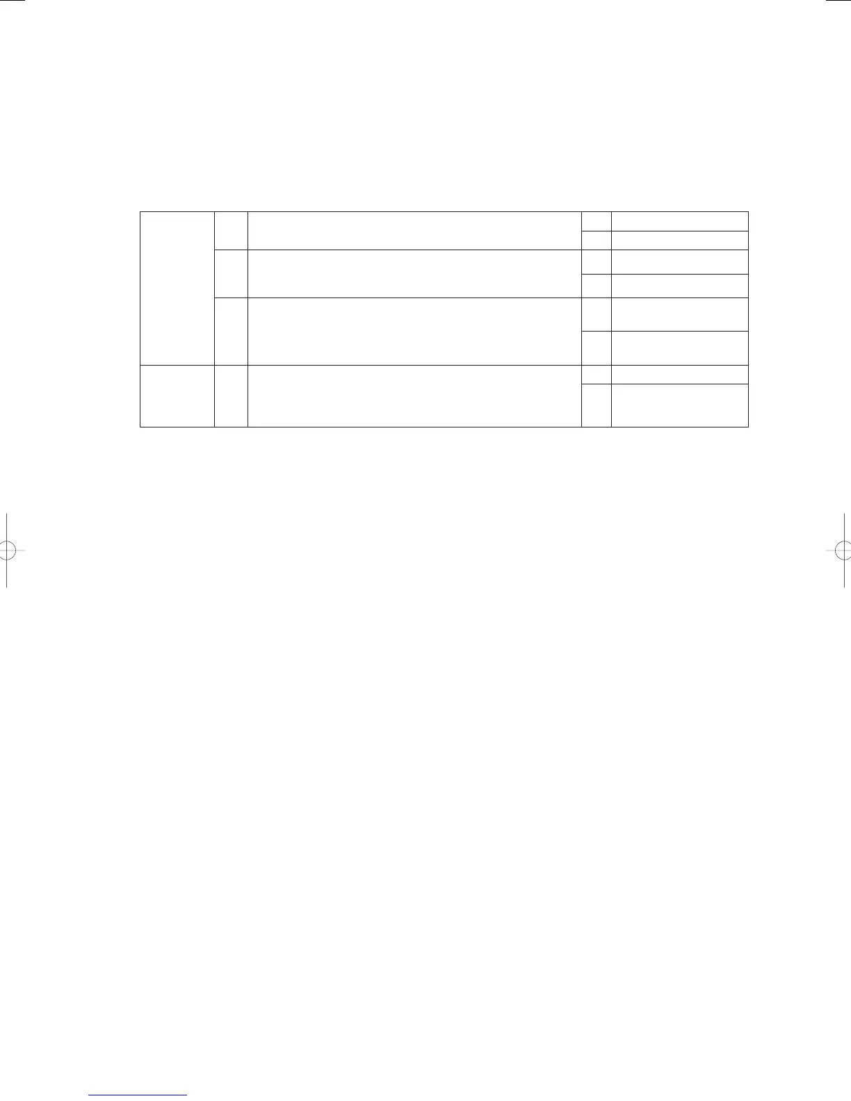
Troubleshooting
1
CT1
(Current
sensor 1)
1-1
Does the wiring from the starter power source magnet switch
(52S) terminal No. 1 pass through CT1 (current sensor)?
Yes 1-2
No Repair wiring
1-2
Use a clamp meter on the R-phase wiring of the starter power
source to measure the current during cranking. Was the
current 5A or more?
Yes 1-3
No 2-1
1-3
Is there a voltage of AC 0.5V or more between outdoor main
board connector 3P (yellow) CN063 No. 1 and No. 3 during
cranking?
Yes
Replace outdoor main
board
No
Replace current sensor
1
2
Starter
power
source
2-1
Broken wire or poor contact in wiring for R and T phases of
starter power source?
Yes Repair wir ing
No
Replace starter power
source
● For work procedure for replacing outdoor main board, see “5. Reference Document”.
● For board and Electrical Wiring Diagram, see Chapter 6.
• Outdoor main board: page VI-2
• Outdoor power board: page VI-3
• Converter board: VI-4
• Indoor control board for DC motor models: page VI-5
• Outdoor Unit Electrical Wiring Diagram: page VI-6* Reference (Electrical Wiring Diagram C - D-1 - 2)
GHPtroubleshooting.indbIV‒17GHPtroubleshooting.indbIV‒17 2012/11/2611:20:072012/11/2611:20:07