IV–58
F01·02·03·10·11 Indoor Unit Temperature Sensor Error
Error detection method
An indoor unit temperature sensor error constantly detects any broken wires or short circuits, and an error is
determined when error conditions are met once.
Error conditions are given below.
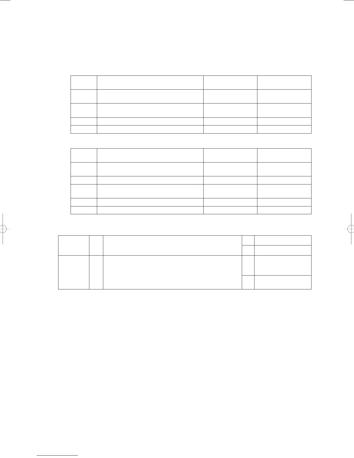
1) With indoor unit connected
Display Sensor name
Broken wire detection
resistance
Short-circuit detection
resistance
F01
Indoor heat exchanger inlet temperature sensor
(E1)
330kΩ or more Less than 30Ω
F03
Indoor heat exchanger outlet temperature
sensor (E3)
330kΩ or more Less than 30Ω
F10 Indoor unit intake temperature sensor 270kΩ or more Less than 24Ω
F11 Indoor unit discharge temperature sensor 270kΩ or more Less than 24Ω
2) With water heat exchanger unit connected
Display Sensor name
Broken wire detection
resistance
Short-circuit detection
resistance
F01
Water heat exchanger refrigerant inlet
temperature sensor (E1)
330kΩ or more Less than 30Ω
F02 Water heat exchanger anti-freeze sensor (E2) 330kΩ or more Less than 30Ω
F03
Water heat exchanger refrigerant outlet
temperature sensor (E3)
330kΩ or more Less than 30Ω
F10 Hot and cold water inlet sensor 270kΩ or more Less than 24Ω
F11 Hot and cold water outlet sensor 270kΩ or more Less than 24Ω
Troubleshooting
1) When the indoor unit is connected
1
Check
wiring
1-1
Poor connection/contact/crimping or broken wire or pinched
wire in sensor connector and wiring?
Yes Repair wiring
No 2-1
2
Check
temperature
sensor
2-1
Disconnect the sensor connector and measure the resistance
value. Is the resistance between the broken wire detection
value and the short-circuit detection value?
Yes
Replace indoor (water
heat exchanger unit)
control board
No
Replace temperature
sensor
● See instructions packaged with servicing indoor board for procedure on replacing indoor control board.
● For board and Electrical Wiring Diagram, see Chapter 6.
• Outdoor main board: page VI-2
• Outdoor power board: page VI-3
• Converter board: VI-4
• Indoor control board for DC motor models: page VI-5
• Outdoor Unit Electrical Wiring Diagram: page VI-6
GHPtroubleshooting.indbIV‒58GHPtroubleshooting.indbIV‒58 2012/11/2611:20:112012/11/2611:20:11