IV–1
4. Error Display and Troubleshooting
The description of each error display begins on a new page. Descriptions of some troubleshooting procedures span
several pages. When you refer to an error display, be sure to fi rst check whether the description of the troubleshooting
procedure spans several pages.
(1) Precautions before Troubleshooting
In order to ensure correct diagnosis and prevent accidents (electric shock, equipment malfunction, measuring
instrument damage, etc.), be sure to observe the following precautions.
Be sure to use a digital tester for voltage measurement
Avoid using a tester with an indicator needle to prevent large measurement errors or operation failure.
Unless otherwise specifi ed, perform voltage measurement with the terminal (terminal plate and connector)
connected
In some cases, measurement is also performed with the terminal disconnected.
Perform continuity measurement (resistance measurement) after disconnecting the terminals on both ends
Performing continuity measurement while the terminals are connected will cause a short circuit or damage to
the tester.
If instructed to disconnect wires before performing continuity or voltage measurement, be sure to do so, then
reconnect the wires before proceeding to the next step (item)
Be sure to turn off the power before connecting or disconnecting wires
Be careful not to touch any live parts (energized components) with a hand or tool while performing voltage
measurement
For DC voltage measurement, the polarity is indicated by + or - after the terminal name (symbol) to prevent
confusion
Connect the red lead of the tester to the + side and the black lead to - side.
(2) About the Error Detection Procedure
Some abnormal occurrences are determined as abnormalities the fi rst time they are detected and some are not
determined to be abnormalities until they are detected multiple times.
In the latter case, the engine is not forced to shut down the fi rst time an abnormal occurrence happens. Instead,
data on the abnormal occurrence is stored in nonvolatile memory, the engine is force stopped for a period of 3
minutes, and then the engine enters the restart sequence.
In the error detection procedures described on the subsequent pages, abnormal occurrences that are determined
as abnormalities after being detected multiple times (e.g. 5 times) are taken to mean abnormal occurrences that
are continually detected multiple times (e.g. 5 times) within 1 hour of engine operation. Regardless of continual
occurrence and engine operation time, the cumulative number of occurrences (e.g. 5 times) may force the engine
to shut down.
(3) Engine Start Standby
● When the engine is in standby mode waiting for the startup conditions to be met, the conditions that have not
yet been met are displayed on the 7-segment LED display.
● There are 6 startup conditions. Some conditions start the engine automatically after a specifi ed time period,
while others cause it to stop with a warning.
● Display Method
The startup conditions (see table below) light at engine start up (No. 0 normal display only)
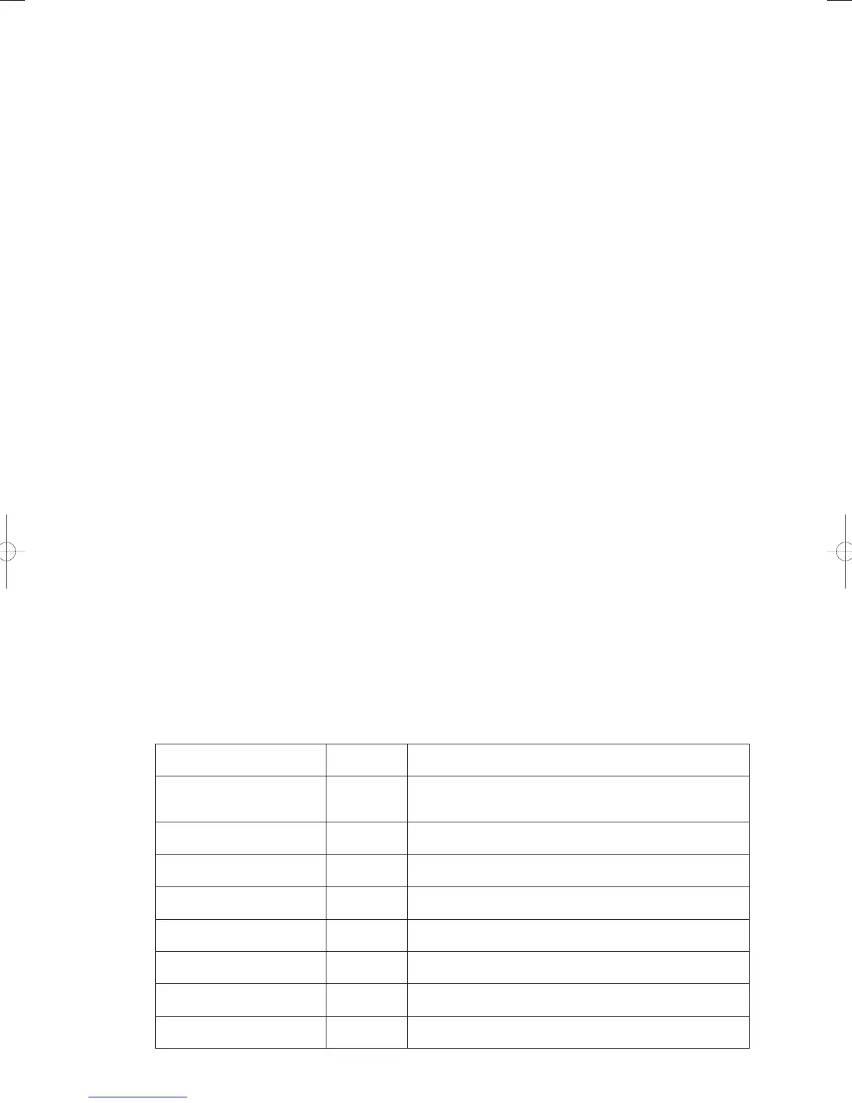
● Startup Conditions Displayed in Engine Start Standby Mode
Start condition
Start Standby
Display Code
Condition
Pressure equalization
(Refrigerant high and low
pressure)
Pressure equalizing display (max. 2 min.)
Compressor outlet temperature
Waiting for the temperature to drop to below 115°C.
(Malfunctioning if the temperature does not drop within 10 minutes.)
Out-of-gas check in progress
Waiting for the compressor inlet pressure to exceed 0.1 MPa.
(Malfunctioning if the pressure is not restored within 10 minutes.)
High coolant temperature
Waiting for the temperature to drop to below 80°C.
(Malfunctioning if the temperature does not drop within 10 minutes.)
Air mix check
Checking that air in the coolant circuit is being mixed (requires a
maximum of approximately 2 minutes.)
Coolant circuit check in progress
Waiting for the coolant pump to exceed 2500rpm
-1
.
(Malfunctioning if the pressure is not restored within 3 minutes.)
No condenser
(3WAY model only)
Waiting for the 3WAY solenoid valve in the indoor and outdoor units
to complete switching so the system can secure the condenser.
No evaporator
(3WAY model only)
Waiting for the 3WAY solenoid valve in the indoor and outdoor units
to complete switching so the system can secure the condenser.
GHPtroubleshooting.indbIV‒1GHPtroubleshooting.indbIV‒1 2012/11/2611:20:052012/11/2611:20:05