V–53
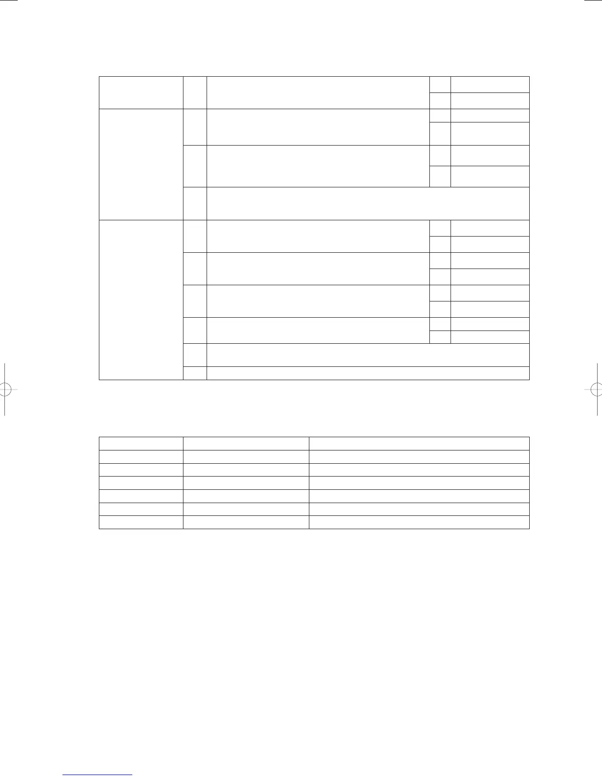
(10) Checks Prior to Automatic Addressing
* When an outdoor unit alarm is displayed, perform the following checks after troubleshooting.
1
Indoor/outdoor power
source
1-1 Indoor and outdoor units turned on?
Yes 2-1
No Turn on the power
2
Indoor/outdoor control
wires
2-1
Have the inside/outside control wires been laid? Is there a
break or disconnection of wires?
Yes 2-2
No
Wiring and
connection
2-2
Was a high voltage (200 V AC), etc. applied to the control
wire circuit?
Has a fuse on the control board blown?
[Confi rmation of each outdoor and indoor unit]
Yes 2-3
No 3-1
2-3
There is a problem with the wiring of the power cable and indoor/outdoor control wires.
Turn off the power, check and repair faulty wiring, and then connect all indoor/outdoor
control wires to the backup control board and controller.
3
Outdoor settings 3-1
Does the setting of connected indoor unit count (No. 10)
on the outdoor control board match the actual count of
connected indoor units?
Yes 3-2
No Correct the setting
3-2
Are the indoor/outdoor control wires connected to multiple
outdoor units?
(Wire-linked?)
Yes 3-3
No 3-6
3-3
Is S010 (terminal resistor ON/OFF switch) on the outdoor
main board set to ON for only one outdoor unit and set to OFF
for all other outdoor units *1?
Yes 3-4
No Correct the setting
3-4 Are there any duplicate settings for outdoor units?
Yes 3-5
No 3-6
3-5
For link wiring, set a system address for each outdoor unit in the order of 1, 2, 3, and then
perform automatic addressing.
3-6 Perform automatic addressing.
*1: Terminal resistor is basically “ON(SHORT)” for one unit only, but depending on the installation status can be
set to “ON(SHORT)” for up to 3 units.
•2-3
Backup connectors and terminals for indoor/outdoor control wires (for communication)
Equipment Primary Backup
Outdoor Unit CN045 (for communication) CN046 (EMG)
Indoor unit CN040(0C) CN044(EMG)
System controller Terminal block No. A7 and B7 Terminal plate No. 3 (Indoor/outdoor backup control wire)
Multi-controller Terminal plate No. 2 (U2) Terminal block No. 3
Intelligent controller Terminal block No. 2 Terminal block No. A6 and B6
AMY adapter JP3-A side JP3-B side
* For a system linking wiring systems, if the systems are connected to water heat exchange unit, depending on
the state of the hot / cold water, automatic address alarm may occur.
If this happens, remove the link wiring and set address individually.
GHPtroubleshooting.indbV‒53GHPtroubleshooting.indbV‒53 2012/11/2611:20:252012/11/2611:20:25