IV–82
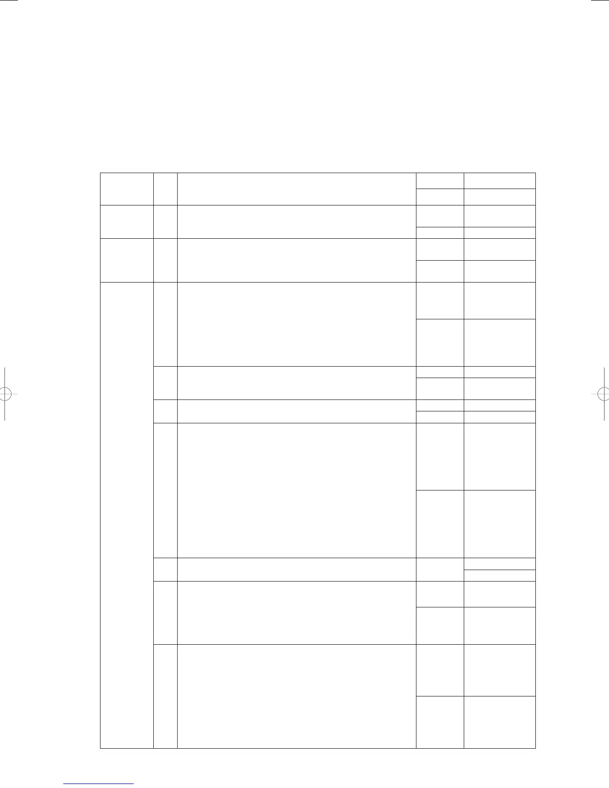
P03 High Compressor Discharge Temperature
Error detection method
• When the compressor discharge temperature ≥ 130°C during engine operation (complete combustion), the
engine is stopped and an error fl ag is set.
A Compressor Discharge Temp. High fault is assumed when this fl ag has shut down the engine 5 consecutive
times.
• Revolution speed setting > minimum revolution speed is not included in pre-trip.
• Not included in pre-trip when liquid valve opening ≤ 400 step.
Troubleshooting
1
Sensor 1-1
Disconnect compressor outlet temperature sensor connector
2P (red) CN054 and measure resistance. Appropriate value?
(See “5. Reference Document” for thermistor characteristics.)
Yes 2-1
No Replace sensor
2
Out of gas
2-1
Out of gas? Determine using compressor outlet pressure,
compressor inlet pressure, and indoor/outdoor electric valve
opening.
Yes
Repair leak and
charge gas.
No 3-1
3
Tubing
3-1
Any symptoms of pump down? Determine with indoor coil
temperature
Yes
Inspect indoor
unit tubing
No
Inspect outdoor
unit tubing
4
Inspect
outdoor
solenoid
valves (For
three-way
device)
4-1
Adjust outdoor solenoid valves. Use trial operation mode
to check that the solenoid valves operate normally in
each operating mode (cooling/heating) and measure
tube temperature around solenoid valves to assess. (For
information on solenoid valve operation in each operating
mode, see the sections Control functions - Operating control
in the “Outdoor unit manual.” Does the solenoid valve operate
normally?
Yes
Replace outdoor
main board
No 4-2
4-2
Adjust the power board.
Does the power board CN013 output the solenoid power
supply voltage (AC 200V)?
Yes 4 - 3
No
Replace power
board
4-3
Any poor connection and broken wires in wiring between the
power board and the relay board?
Yes Repair wir ing
No 4-4
4-4
Adjust the outdoor main board.
In No. 4 test mode when “v_open” (valve open), is there a
drive output voltage (12 V DC) from discharge valves 1-1, 1-2,
discharge valve 2, suction valve 2-1 and 2-2?
(9P (white) CN018)
Discharge valve 1-1, 1-2: between No. 3 - 9 Discharge valve 2:
between No. 4-9
Suction valve 2-1, 2-2: between No. 6 - 9
Does suction valve 1 output a drive voltage (DC 12V) during
cooling operation?
Suction valve 1: between No. 3 - 9
* Note that suction valve 1 closes when powered (the other
valves operate in the opposite way)
Yes 4 - 5
No
Replace outdoor
main board
4-5
Any poor connection and broken wires in wiring between the
outdoor main board and the relay board?
Repair wiring
4-6
4-6
Adjust the relay board.
In No. 4 test mode when “v_open” (valve open), is there an
output voltage (AC 200V) from discharge valves 1-1, 1-2,
discharge valve 2, suction valve 2-1 and 2-2?
Does suction valve 1 output a voltage (AC 200V) during
cooling operation?
Yes 4 -7
No
Replace relay
board
4-7
Adjust the solenoid valve coil.
(Be sure to turn the power off before starting work.)
Disconnect the connectors of discharge valve 1-1, 1-2,
discharge valve 2, suction valve 1, suction valve 2-1 and 2-2
from the relay board and measure the resistance between No.
1 and 3.
Normal value (20°C) discharge valve 1-1, 1-2: 543 ohm
discharge valve 2: 1132 ohm
Suction valve 1: 1197 ohm suction valve 2-1, 2-2: 543 ohm
Is the coil operating normally?
Resistance
is normal
Replace solenoid
valve
Abnormal
resistance
Replace the
solenoid valve
coil
GHPtroubleshooting.indbIV‒82GHPtroubleshooting.indbIV‒82 2012/11/2611:20:132012/11/2611:20:13