IV–19
A20 High Coolant Temperature
Error detection method
When the coolant temperature
≥
100°C continuously for 2 seconds or when the coolant temperature is
≥
95°C for
3 consecutive seconds during engine operations (complete combustion,) the engine will be momentarily shut
down and an error fl ag set.
The reason for the engine shutting down is because the error fl ag was set fi ve times consecutively.
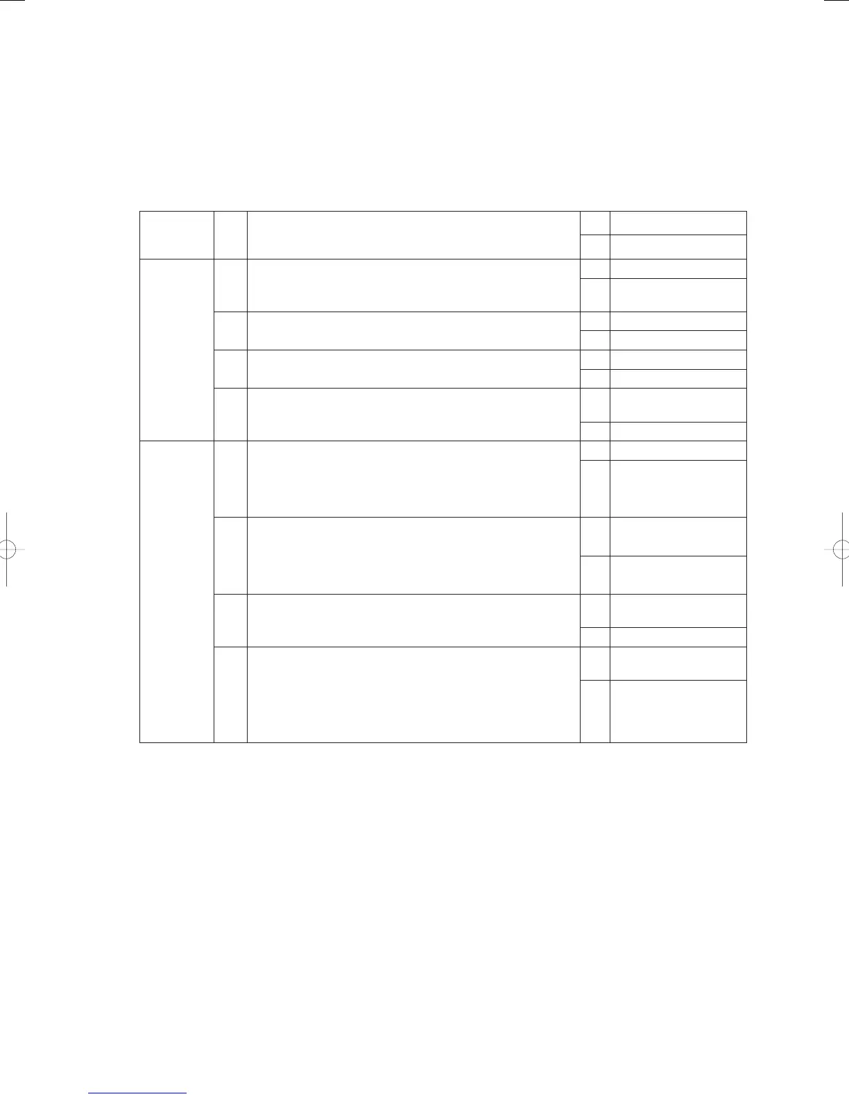
Troubleshooting
1
Pump
rotation
1-1 Is the coolant pump rotating during operations?
Yes 2-1
No See A22
2
Coolant
circuit
2-1
Is the three-way electric coolant valve at the engine outlet
operating normally?
Yes 2-2
No
Repair or replace the
three-way valve
2-2
Are there any signs of coolant discharge from the reserve
tank?
Yes 2- 4
No 2-3
2-3 Is there air in the coolant?
Yes Purge the air
No 3-1
2-4 Is coolant leaking or seeping, etc., from the coolant hose?
Yes
Purge the air after
repairs
No Purge the air
3
Sensor
check 3-1
Disconnect relay connector 2P-12 (green) on the coolant
temperature sensor and then measure the resistance.
Measure the surface temperature and compare the results.
(See “5. Reference Document” for details on thermistor
characteristics.)
OK 3-2
NG
Replace the coolant
temperature sensor
3-2
When the coolant temperature sensor relay connector has
been reconnected, display the coolant temperature (No.
0dAtA data code 20) on the 7-segment LED on the outdoor
unit’s main board. Compare this to the actual temperature
measured on the surface.
OK 3-4
NG 3-3
3-3 Is there any water, etc. on relay connector 2P-12 (green)?
OK
Replace the outdoor
unit’s main board
NG Repair
3-4
Is the exhaust heat collection valve locked closed during
heating operations?
(This does not need to be checked if A20 occurred in the
cooling mode.)
OK
Replace the outdoor
unit’s main board
NG
Replace the exhaust
heat collection valve
(motor-operated valve
ASSY)
● For work procedure for replacing outdoor main board, see “5. Reference Document”.
● For board and Electrical Wiring Diagram, see Chapter 6.
• Outdoor main board: page VI-2
• Outdoor power board: page VI-3
• Converter board: VI-4
• Indoor control board for DC motor models: page VI-5
• Outdoor Unit Electrical Wiring Diagram: page VI-6
* Reference (Electrical Wiring Diagrams A - B-3: coolant pump)
(Electrical Wiring Diagrams D - E: sensor)
• 2-1
Three-way electric coolant valve inspection
1) Operate the engine in the cooling mode, and measure the surface temperature of tubing fl owing to the 2F
outdoor heat exchanger.
2) Confi rm that the coolant temperature is rising, and that the coolant is fl owing toward 2F.
First opened: 70°C / Fully open: 80°C
GHPtroubleshooting.indbIV‒19GHPtroubleshooting.indbIV‒19 2012/11/2611:20:072012/11/2611:20:07