IV–6
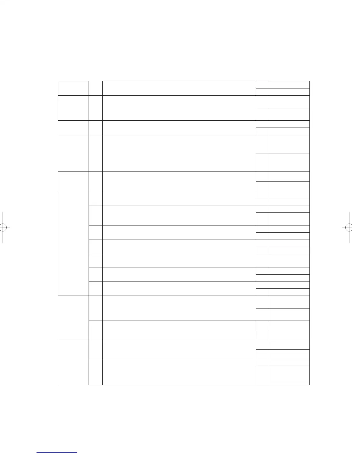
A04 Engine Low-Revolution Error
Error detection method
• When engine revolution speed drops to 700min
-1
or less continuously for 3 seconds during engine operation
(complete combustion), an abnormal fl ag is set and the engine stops. An Engine Speed Too Low condition is
assumed when the error fl ag has stopped the engine 5 consecutive times in 1 hour.
Troubleshooting
1
Fuel
1-1 Has the fuel gas pressure dropped? Is the fuel empty?
OK 2-1
NG Restore
2
Check
revolution
speed
2-1
Measure actual revolution speed using a revolution meter. Are the
revolutions low?
Yes 3 -1
No 4-1
3
Mixer
3-1 Is the throttle valve operating?
Yes 6 -1
No 5-1
4
Ignition
pulse
4-1
Check the ignition coil, cam angle sensor, and crank angle sensor.
Check the ignition coil → Remove the connectors from the ignition
coil one by one during operations. It is normal if changes in
operational status, such as lowered revolutions, occur.
Cam angle & crank angle sensors → Refer to A23 and A24 for
inspections.
OK 5-1
NG Restore
5
Wiring 5-1
Any poor connections, poor contacts or severed wires between the
throttle (step motor) wiring and connector? (Wiring from outdoor main
board connector 6P (black) CN066 to throttle (step motor))
Yes Repair Wiring
No 8-1
6
Engine
6-1 Measure compression (See A06 5-1).
OK 6-3
NG 6-2
6-2
Check 6-1 again after washing the valve and adjusting the valve
clearance. Any problem with compression?
OK 6-3
NG
Replace engine
head
6-3 Are spark emissions normal?
Yes 6 - 6
No 6-4
6-4 Inspect ignition plug (see A06 2-3)
OK 6-5
NG Replace
6-5
Replace the ignition coil, cam angle sensor and crank angle sensor one by one to identify the
defective part.
6-6 Inspect the zero governor (see A06 3-1).
OK 6-7
NG Restore
6-7 Is the ignition timing normal? (see A06 5-4)
OK 7-1
NG Adjust
7
Fuel gas
regulating
valve
7-1
Does the fuel regulating valve (step motor) coil resistance measure
about 120Ω? (Disconnect relay connector 6P-6 and measure
between No. 1 (red) and No. 2/No. 3, and between No. 4 (orange)
and No. 5/No.6.)
OK 7-2
NG Replace mixer
7-2
Is 4V DC being applied between the outdoor main board connector
6P (red) CN065 No. 5 and No. 1/No. 2 as well as between No. 3/No.
4 when the power is on (during positioning)?
Yes Replace mixer
No 8-1
8
Mixer 8-1
Does the throttle (step motor) coil resistance measure about 120Ω?
(Disconnect relay connector 6P-2, and measure between No. 1 (red)
and No. 2/No. 3, and between No. 4 (orange) and No. 5/No. 6.)
Yes 8 -2
No Replace mixer
8-2
Is 4V DC being applied between the outdoor main board connector
6P (black) CN066 No. 1 (+) and No. 2 (-)/No. 3 (-) as well as between
No. 4 (+) and No. 5 (-)/No. 6 (-) when the power is on (during
positioning)?
Yes Replace mixer
No
Replace the
outdoor unit’s
main board
● For work procedure for replacing outdoor main board, see “5. Reference Document”.
● For board and Electrical Wiring Diagram, see Chapter 6.
• Outdoor main board: page VI-2
• Outdoor power board: page VI-3
• Converter board: VI-4
• Indoor control board for DC motor models: page VI-5
• Outdoor Unit Electrical Wiring Diagram: page VI-6
GHPtroubleshooting.indbIV‒6GHPtroubleshooting.indbIV‒6 2012/11/2611:20:062012/11/2611:20:06