IV–12
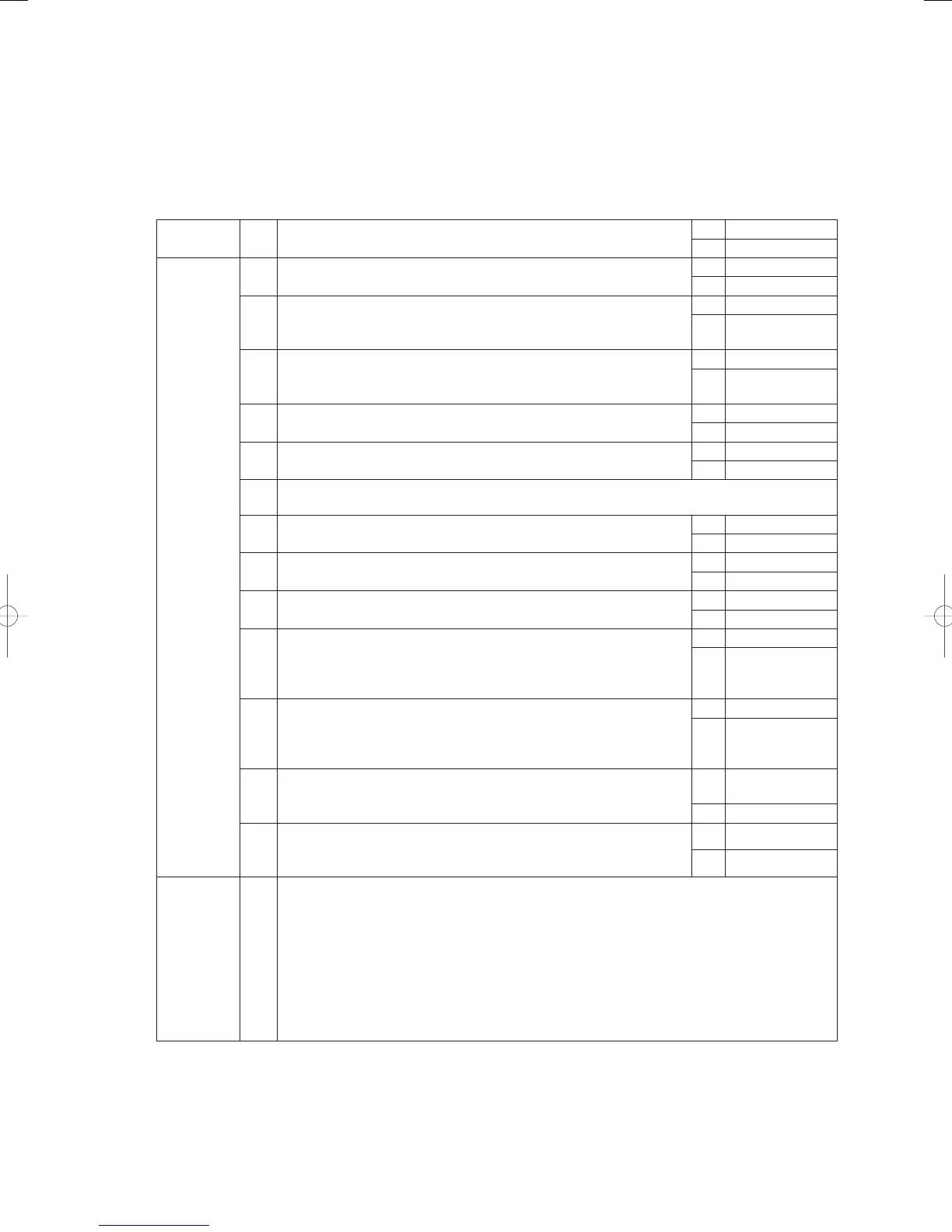
A08 Engine Stall
Error detection method
During engine operation (complete combustion), when engine revolution speed ≤ 100min
-1
continuously for 3
seconds, the engine is stopped momentarily and an error fl ag is set.
An Engine Stall condition is assumed when the error fl ag has stopped the engine 5 consecutive times in 1 hour.
Troubleshooting
1
Fuel
1-1 Has the fuel gas pressure dropped? Is the fuel empty?
OK 2-1
NG Restore
2
Engine
2-1 Measure compression (See A06 5-1).
OK 2-3
NG 2-2
2-2
Check 2-1 again after washing the valve and adjusting the valve
clearance.
Any problem with compression?
OK 2-3
NG
Replace engine
head
2-3 Is the air cleaner soiled? (Visual inspection)
OK 2-4
NG
Clean and
Replace
2-4 Are spark emissions normal?
Yes 2-7
No 2-5
2-5 Inspect ignition plug (see A06 2-3)
OK 2-6
NG Replace
2-6
Replace the ignition coil, cam angle sensor and crank angle sensor one by one to identify the
defective part.
2-7 Inspect the zero governor (see A06 3-1).
OK 2-8
NG Restore
2-8 Is the ignition timing okay? (see Chapter 5 (9)).
OK 2-9
NG Adjust
2-9 Is air being sucked in? Check the rubber plug on the intake manifold.
OK 2-10
NG Replace
2-10
Is 4V DC (approximately) being applied between outdoor unit’s main
board connector 6P (black) CN066 No. 1 (+) and No. 2 (-)/No. 3
(-) and between No. 4 (+) and No. 5 (-)/No. 6 (-) when the power is
turned on (during positioning)?
Yes 2-11
No
Replace the
outdoor unit’s
main board
2-11
Is DC voltage being applied between outdoor unit’s main board
connector 6P (red) CN065 No. 1 (+) and No. 2 (-)/No. 3 (-) and
between No. 4 (+) and No. 5 (-)/No. 6 (-) when the power is turned on
(during positioning)?
Yes 2-12
No
Replace the
outdoor unit’s
main board
2-12
Inspect the mixer’s stepping motor (both the throttle and the fuel gas
adjustment valve.) Are any wires severed?
Yes
Replace the
stepping motor
No 2-13
2-13
Are the throttle valve or fuel gas adjustment valves locked in place?
Is it possible to easily move each valve by hand with the stepping
motor removed?
Yes 3 -1
No Replace mixer
3
Engine load
check
3-1
There is a chance that the engine load could be unsuitable. Check the following, and make
repairs if problems are found.
• Is the air fi lter on the indoor unit blocked? (Especially in the heater mode.)
• Has a short circuit occurred with the air on the indoor unit? (Especially in the heater mode
with the remote controller’s thermostat.)
• Has a short circuit occurred with the air on the outdoor unit, or is the air heat exchanger on
the outdoor unit closed, etc.? (When in the cooler mode.)
• Is the refrigerant route blocked (strainer, dry core, etc.), is the valve closed (forgotten to open
closed valves, etc.,) or is the motor-operated valve locked in place?
• Has the refrigerant been over-fi lled?
● For work procedure for replacing outdoor main board, see “5. Reference Document”.
● For board and Electrical Wiring Diagram, see Chapter 6.
• Outdoor main board: page VI-2
• Outdoor power board: page VI-3
• Converter board: VI-4
• Indoor control board for DC motor models: page VI-5
• Outdoor Unit Electrical Wiring Diagram: page VI-6
GHPtroubleshooting.indbIV‒12GHPtroubleshooting.indbIV‒12 2012/11/2611:20:062012/11/2611:20:06