IV–77
L16 Faulty Water Heat Exchanger Unit Settings
* Only detected when the water heat exchanger unit is connected.
Re-check the settings if it is not the relevant model.
Error detection method
An error is determined in accordance with the criteria shown below the fi rst time the settings on the water heat
exchanger unit’s control board are incorrect.
• When the temperature during heating with SW4 and 5 is outside of the temperature setting.
• When the temperature during cooling (water) with SW1 to 3 is outside of the temperature setting.
• When the temperature during cooling (brine) with SW1 to 3 is outside of the temperature setting.
• When the setting for the anti-icing control switch with SW8-1 is incorrect.
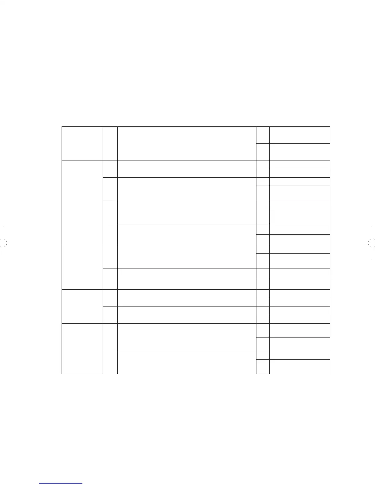
Troubleshooting
1
Set temperature
check during
heating
1-1
Are the settings for SW4 and SW5 between 35°C and
55°C?
Yes 2-1
No Revise settings
2
Set temperature
check during
cooling (water)
2-1 Is it used as a water chiller?
Yes 2-2
No 3-1
2-2 Is SW1-2 set at OFF?
Yes 2-3
No
Proceed to 2-3 after
changing to OFF
2-3 Is SW1-3 set at OFF?
Yes 2- 4
No
Proceed to 2-4 after
changing to OFF
2-4
Are the settings for SW2 and SW3 between 5°C and 15°C?
(If the answer is “No” for either 2-2 or 2-3, diagnostics will
end even if 2-4 is “Yes.”)
Yes 4-1
No Revise settings
3
Set temperature
check during
cooling (brine)
3-1 Is SW1-2 set at ON?
Yes 2-2
No
Proceed to 2-2 after
changing to ON
3-2
Are the settings for SW1, SW2 and SW3 between -15°C
and 15°C? (If the answer is “No” for 3-1, diagnostics will
end even if 3-2 is “Yes.”)
Yes 4-2
No Revise settings
4
Anti-icing
control switch
setting check
4-1 Is SW8-1 set at OFF?
OK 5-1
NG Change to OFF
4-2 Is SW8-1 set at ON?
OK 5-1
NG Change to ON
5
Miscellaneous
5-1
Momentarily reverse (switch to the opposite sides) all dip
switches (SW1-2. SW1-3, SW1-8) and then try returning
them to their previous positions. Has the problem been
solved?
Yes End diagnostics
No 5-2
5-2
Move the position of the rotary switches (SW2 to 5) around
at random, and then try returning them to within the set
range. Has the problem been solved?
Yes End diagnostics
No
Replace the control
board
● For details on the procedures for replacing the water heat exchanger unit’s control board, see Chapter 5
“Reference Document.”
● For details on board and electrical wiring diagrams, see Chapter 6.
● 1-1
Set SW4 at tens place and SW5 at ones place. The set temperature range is between +35°C and +55°C.
(Example: If SW2 is set at “4” and SW3 at “5”, the set temperature is “+45°C”.)
GHPtroubleshooting.indbIV‒77GHPtroubleshooting.indbIV‒77 2012/11/2611:20:122012/11/2611:20:12