IV–50
E15 Automatic Address Alarm (Too Few Units)
1) When the indoor unit is connected
Error detection method
An error is determined when the indoor unit count responding to transmission is less than the indoor unit
count set on the outdoor unit. (Also detected apart from auto-addressing.)
• The actual number of indoor units is less than the number of indoor units set on the outdoor unit.
• Connected indoor unit power is OFF
• An indoor unit has a short-circuited inspection pin (CN062/CN071) or TEST pin (CN064) upon power
ON.
• High voltage (AC200V, etc) was applied across indoor/outdoor operation wire circuit.
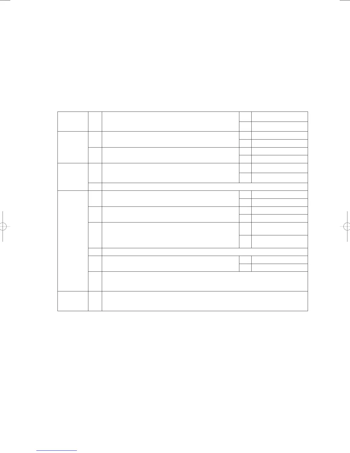
Troubleshooting
1
Power
supply
1-1 Is the indoor unit power OFF?
Yes Turn power ON
No 2-1
2
Indoor/
outdoor
operation
wiring
2-1
Indoor/outdoor operation wiring broken or short-circuited?
(See “5. Reference Document”)
Yes Repair wiring
No 2-2
2-2
High voltage (AC200V, etc) applied across indoor/outdoor
operation wire circuit?
Yes 3-2
No 3-1
3
Indoor unit
count
3-1
Did the number of indoor units change after auto-addressing?
Or, was the indoor unit count setting changed on the outdoor
main board?
Yes 3-2
No 4-1
3-2 Perform pre-check before auto-addressing. (See “5. Reference Document”)
4
Indoor
control
board
4-1
Is the inspection pin (CN062/CN071) or TEST pin (CN064) on
the indoor control board short-circuited?
Yes Eliminate short-circuit
No 4-2
4-2
Is an option board (CN060) or wireless remote controller
(CN041) connected to the indoor control board?
Yes 4 - 3
No 4-5
4-3
Does E15 disappear several minutes after disconnecting said
connector on the indoor control board? (When controlling with
two remote controllers and the wireless remote controller is
the main, set the other remote controller as the main).
Yes 4 - 4
No 4-5
4-4 Replace the removed option board or wireless remote controller operating unit, wiring and all.
4-5 Is the LED blinking on the indoor control board?
Yes 4-6
No 5-1
4-6
Nonvolatile memory (EEPROM) on the outdoor main unit is not inserted, is incorrectly
inserted or is defective → Correct or replace nonvolatile memory and program it in the remote
controller properties setting mode.
5
Outdoor
main board
5-1
On the outdoor main board, use setting No. 10 to set the indoor unit count. Then compare the
indoor unit connection status using No. 9 (indoor unit check), and investigate the unaccounted
indoor unit in detail.
● The designation (/) is used in the table to indicate indoor boards for DC and AC motor models.
● There is no TEST pin on the indoor board for AC motor models.
● See “5. Reference Document” for checking remote controller.
● For board and Electrical Wiring Diagram, see Chapter 6.
• Outdoor main board: page VI-2
• Outdoor power board: page VI-3
• Converter board: VI-4
• Indoor control board for DC motor models: page VI-5
• Outdoor Unit Electrical Wiring Diagram: page VI-6
● See instructions packaged with servicing indoor board for procedure on replacing indoor non-volatile
memory (EEPROM) and replacing indoor control board.
* In systems that link wiring systems where a water heat exchanger unit is connected, the state of hot and cold
water may output an Automatic Address Setting Warning.
Should this happen, remove link wiring and set a different address.
GHPtroubleshooting.indbIV‒50GHPtroubleshooting.indbIV‒50 2012/11/2611:20:102012/11/2611:20:10