IV–51
2) When the water heat exchanger unit is connected
Error detection method
An error may be assumed when the outdoor unit’s connection setting on the indoor unit is incorrect, and
when an error exists in the connected equipment or when an error exists because the power has not been
switched on, etc.
(The number of indoor units connected must be set at two on the outdoor unit when a water heat exchanger
unit is connected.)
• The setting for number of indoor units connected is set at three or more on the outdoor unit.
• The power to the connected water heat exchanger unit has not been switched on.
• High voltage (AC200V, etc.) has been applied to the indoor/outdoor operation wiring circuit.
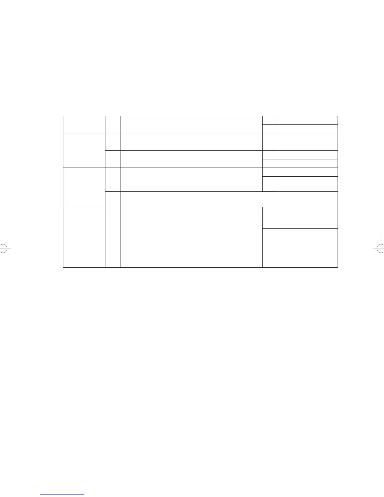
Troubleshooting
1
Power supply
1-1
Is the power to the water heat exchanger unit’s switched
off?
Yes Switch on the power
No 2-1
2
Indoor/outdoor
operation wiring
2-1
Is the indoor/outdoor operation wiring severed or short-
circuited?
Yes Repair Wiring
No 2-2
2-2
Is high voltage (AC200V, etc.) being applied to the indoor/
outdoor operation wiring circuits?
Yes 4-1
No 3-1
3
Water heat
exchanger unit
count
3-1
Has the number of connected indoor units set with the
No.10 parameter on the outdoor unit’s main board been
amended to a fi gure other than two?
Yes 3 -2
No
Reset the outdoor unit’s
power supply
3-2
Set the number of connected indoor units to two with the No.10 parameter on the outdoor
unit’s main board.
4
Remote
controller wires
(link wiring
between
the remote
controller and
the water heat
exchanger unit)
4-1
Is the water heat exchanger unit’s control board 2P-13
already in use?
Yes
Replace the water heat
exchanger unit’s control
board
No
Reverse the water heat
exchanger unit’s control
board connectors (2P-12
→ 2P-13)
● See “5. Reference Document” for details on the procedure for replacing the water heat exchanger unit’s
control board.
● For board and Electrical Wiring Diagram, see Chapter 6.
• Outdoor main board: page VI-2
• Outdoor power board: page VI-3
• Converter board: VI-4
• Indoor control board for DC motor models: page VI-5
• Outdoor Unit Electrical Wiring Diagram: page VI-6
GHPtroubleshooting.indbIV‒51GHPtroubleshooting.indbIV‒51 2012/11/2611:20:102012/11/2611:20:10