IV–7
A05 Ignition Source Error
Error detection method
When the starter power output meets the following conditions, an error is detected upon 5 consecutive
occurrences in one hour.
• When an ignition voltage decrease is detected for 2.5 seconds or more.
• During cranking, when I<3.8A is detected for 4 seconds, with no revolution pulse.
Note) The starter power source magnet switch (52S) operation is as follows.
• When power is turned on, 52S turns ON upon operation signal input. If no abnormalities occur thereafter
(A15, A16, A17), this stays ON, and turns OFF upon stop signal input.
• Turns OFF when error occurs.
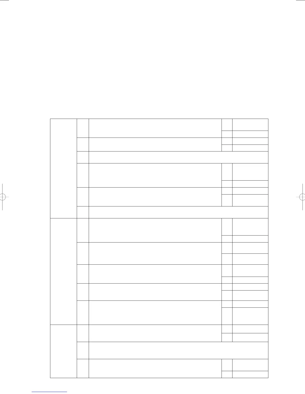
Troubleshooting
Try operating the outdoor unit.
• When the starter power source magnet switch (52S) does not turn ON: Go to 1-1
• When the starter power source magnet switch (52S) turns ON, and then turns OFF after 3 seconds: Go to 2-1
• When the starter power source magnet switch (52S) turns ON but the starter does not turn ON: Go to 4-1
1
Starter
power
source
magnet
switch (52S)
1-1
Is AC200C applied between magnet switches A1 and A2 when the
magnet switch is turned on?
Yes
Replace magnet
switch
No 1-2
1-2
Is AC200C applied between power board connectors 3P (yellow)/
CN028 No. 1 and No.3 when the magnet switch is turned on?
Yes 1-3
No 1-4
1-3
When wiring connection/contact is poor between the outdoor unit’s power board connector 3P
(red)/CN028 and magnet switches A1-A2 → Repair wiring
1-4
Is AC200C being applied between the outdoor unit’s power board
connector 3P (white)/CN002 No. 1 and No. 2?
Yes
Replace the
outdoor unit’s
power board
No 1-5
1-5
Is AC200C being applied between the fi lter board connector 3P
(white)/CN003 No. 1 and No. 2?
Yes 1- 6
No
Replace the fi lter
board
1-6
When wiring connection/contact is poor between the outdoor unit’s power board connector 3P
(white)/CN002 and fi lter board 3P (white) CN003 No.1 and No.3 → Repair wiring
2
Ignition coils
2-1
Is DC11V or more applied between the outdoor unit’s main board
connector 2P (black) CN006 No. 1 (+) and No. 2 (–) when the magnet
switch is turned on?
Yes
Replace the
outdoor unit’s
main board
No 2-2
2-2
Is DC11V or more applied between the outdoor unit’s main board
connector 2P (black) CN006 No. 1 (+) and No. 2 (–) when the magnet
switch is turn on with the outdoor unit’s main board connectors 6P
(white) CN010 and 6P (black) CN011 disconnected?
Yes 2-3
No 2-4
2-3
Check for ground faults or short-circuits between the outdoor unit’s
main board connector 6P (white) CN010 and 6P (black) CN011 and
each ignition coil.
OK
Replace the
ignition coil
NG Repair Wiring
2-4
Is AC11V or more applied between the outdoor unit’s main board
connector 2P (white) CN022 No. 1 (+) and No. 2 (–) when the magnet
switch is turned on?
Yes 2-5
No 3-1
2-5
Are there any defective wiring connections/contacts or severed wires
between the outdoor unit’s power board connector 2P (black) CN025
and the outdoor unit’s main board connector 2P (black) CN006?
Yes Repair Wiring
No
Replace the
outdoor unit’s
power board
3
Ignition
(starter)
power
3-1
Is approximately AC11V applied between the starter power source’s
relay connector 2P-7 (black) No. 1 and No. 2 when the magnet switch
is turned on?
Yes 3 -2
No 3-3
3-2
Are there any defective wiring connections/contacts or severed wires between the outdoor
unit’s power board connector 2P (white) CN022 and the starter power source’s relay
connector 2P-7 (black)? → Repair wiring
3-3
Is AC200V applied between the starter power source’s relay
connector 2P-6 (white) No. 1 and No. 2 when the magnet switch is
turned on?
Yes
Replace the
starter power
No 3-4
GHPtroubleshooting.indbIV‒7GHPtroubleshooting.indbIV‒7 2012/11/2611:20:062012/11/2611:20:06