IV–15
A15 Starter Power Source Output Short Circuit
Error detection method
When the starter power primary current meets the following conditions, an error is determined upon 5
consecutive occurrences in 1 hour.
• Not during cranking: When 40A or more is detected for 0.1 second or more
• Not during cranking: When 26A or more is detected for 0.2 second or more
• Not during cranking: When 3.8A or more is detected for 5.0 second or more
Note 1) The starter power source magnet switch (52S) operation is as follows.
• 52S turns ON upon operation signal input. If no abnormalities occur thereafter (A15, A16, A17), this stays
ON,and turns OFF upon stop signal input.
• Turns OFF when error occurs.
Troubleshooting
1
Starter
power
source (DC
current)
1-1
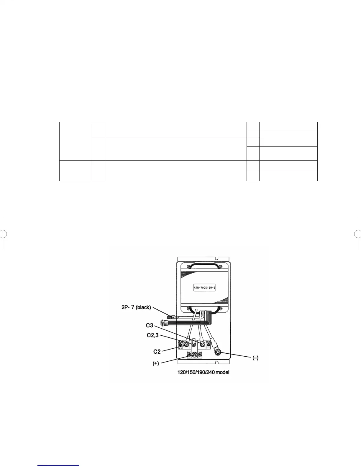
Reoccurs even when disconnecting the two wires from the
starter power sours
⊕
terminals?
Yes 1-2
No 2-1
1-2
Reoccurs even after disconnecting control board connector
3P (yellow) CN063 (Ignore abnormality A17 if it occurs.)
Yes Replace control board
No
Replace starter power
sours
2
Starter 2-1
Is either of the two wires from the starter power sours
⊕
terminal to the starter short-circuit, ground faulted, or
misrouted?
Yes Repair/replace wir ing
No Replace starter
● For work procedure for replacing outdoor main board, see “5. Reference Document”.
● For board and Electrical Wiring Diagram, see Chapter 6.
• Outdoor main board: page VI-2
• Outdoor power board: page VI-3
• Converter board: VI-4
• Indoor control board for DC motor models: page VI-5
• Outdoor Unit Electrical Wiring Diagram: page VI-6 *Reference (Electrical Wiring Diagram C-D-1-2)
• 1 -1, 2-1
GHPtroubleshooting.indbIV‒15GHPtroubleshooting.indbIV‒15 2012/11/2611:20:072012/11/2611:20:07