IV–18
A19 Low Coolant Temperature
Error detection method
• If the temperature of the coolant does not exceed 60°C during engine operations (complete combustion,)
the engine will be momentarily halted. (The time varies between 30 to 60 minutes depending on the
temperature.)
An emergency shutdown will occur when the engine has been halted twice because of this error.
The cumulative number of times will be reset when the coolant maintains a temperature of 60°C or more or
exceeds 85°C.
Troubleshooting
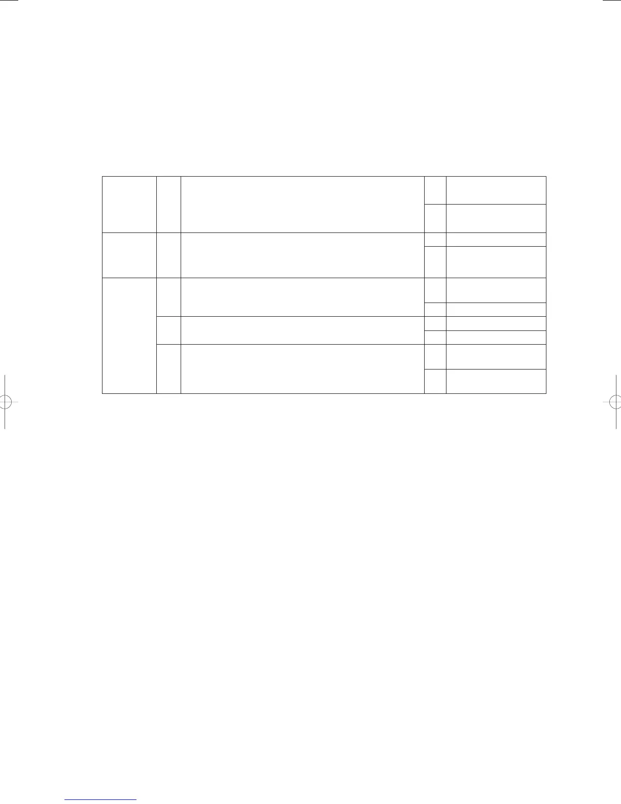
1
Coolant
temperature
sensor
1-1
Disconnect relay connector 2P-12 (green) on the coolant
temperature sensor and then measure the resistance.
Measure the surface temperature and compare the results.
(See “5. Reference Document” for details on thermistor
characteristics.)
OK 2-1
NG
Replace the coolant
temperature sensor
2
Three-way
coolant
valve
2-1
Disconnect the three-way coolant valve and check to see
if it is locked. (Check power source initialization and the
current output with actual valve operations.) Is the valve
malfunctioning?
OK 3-1
NG
Replace the three-way
coolant valve
3
Exhaust
heat
collection
valve
3-1 Is the exhaust heat collection valve locked open?
OK
Replace the outdoor
unit’s main board
NG 3-2
3-2
Is the wiring to the exhaust heat collection valve severed or
short-circuited?
OK 3-3
NG Repair Wiring
3-3
Replace the exhaust heat collection valve (solenoid valve
ASSY) and perform a test run.
Does the coolant temperature rise?
Yes
Keep an eye on the
situation
No
Replace the outdoor
unit’s main board
● For work procedure for replacing outdoor main board, see “5. Reference Document”.
● For board and Electrical Wiring Diagram, see Chapter 6.
• Outdoor main board: page VI-2
• Outdoor power board: page VI-3
• Converter board: VI-4
• Indoor control board for DC motor models: page VI-5
• Outdoor Unit Electrical Wiring Diagram: page VI-6
• 1-1
Resistance values of the coolant temperature sensor (see the chart on thermistor characteristics for further
details.)
40°C: 1.2kΩ 50°C: 879Ω 60°C: 642Ω 70°C: 477Ω
80°C: 361Ω 90°C: 227Ω 100°C: 216Ω
• 3-1
Check to make sure the exhaust heat collection valve is not locked open by following the instructions below.
1) Use the [Off] button on the remote controller to stop the outdoor unit in order to completely close the
exhaust heat collection valve. Note: The valve will not be completely opened if the [STOP-SW] on the
outdoor unit’s main board is used to halt operations. The [Off] switch on the remote controller or the
enforced thermo-off switch on the outdoor unit’s main board must be used without fail.
2) Disconnect the connector (CN0725P white) on the exhaust heat collection valve after three or more
minutes have elapsed since the outdoor unit was powered off.
3) Resume operations of the outdoor unit in the heater mode. (Either as a test run or with remote controller
operations.)
4) Once the outdoor unit is operating, measure the temperature of the exhaust heat collection valve’s
secondary duct for approximately two minutes.
5) If it is clear that the temperature has dropped in comparison with the situation before start-up, then there
is a chance that the valve is locked open. Everything is normal if the temperature does not drop.
Note: Keep the operation time to a maximum of fi ve minutes.
6) Once the inspection is completed, make sure the exhaust heat collection valve connector is reconnected
and the power source reset.
* If the power source is not reset, it will be impossible for the exhaust heat collection valve to be positioned,
which will hinder subsequent operations.
GHPtroubleshooting.indbIV‒18GHPtroubleshooting.indbIV‒18 2012/11/2611:20:072012/11/2611:20:07