IV–37
E04 Indoor Unit Receive Failure from Outdoor Unit
1) When the indoor unit is connected
Error detection method
After turning power ON, with no transmission from outdoor unit for 3 minutes. Or, an error is determined
when the outdoor unit does not respond.
• Outdoor unit power is OFF.
• With link wiring, when outdoor main board terminal resistor switch (S7) is set to “ON” for several units.
• When turning power ON after completing auto-addressing, when the number of indoor units has changed.
• When indoor unit power is not ON.
• Inspection pin (CN062/CN071) or TEST pin (CN064) on the indoor control board is short-circuited.
• Non-volatile memory (EEPROM) is not inserted when changing indoor board.
• In the remote controller detailed settings mode, the indoor address is “undetermined”.
• Indoor unit addresses duplicated
• Indoor/outdoor operation wiring is short-circuited or broken.
• Error in the reception circuit on the signal output board (option board)
• Breakdown of outdoor unit
• High voltage (AC200V, etc) applied across indoor/outdoor operation wire circuit
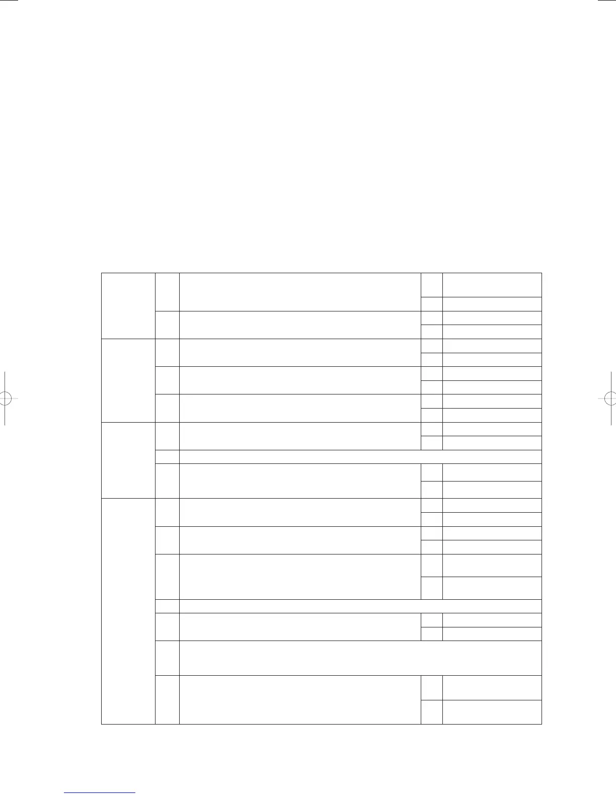
Troubleshooting
1
Power
supply
1-1 Is/was the outdoor unit power OFF?
Yes
Turn power ON and wait
3 minutes
No 1-2
1-2 Is the indoor unit power OFF?
Yes Turn power ON
No 2-1
2
Indoor/
outdoor
operation
wiring
2-1
Indoor/outdoor operation wiring broken or short-circuited?
(See “5. Reference Document”)
Yes Repair wir ing
No 2-2
2-2
With link wiring, is the outdoor main board terminal resistor
switch (S010) set to “ON” for several units?
Yes Set only one unit to “ON”
No 2-3
2-3
High voltage (AC200V, etc) applied across indoor/outdoor
operation wire circuit?
Yes 3 -2
No 3-1
3
Indoor unit
count
3-1
Did the number of indoor units increase or decrease after
auto-addressing?
Yes 3 -2
No 3-3
3-2 Perform pre-check before auto-addressing. (See “5. Reference Document”)
3-3
In the remote controller detailed settings mode, check the
indoor unit address (item code 13). Any undetermined (99) or
duplicated addresses for indoor units?
Yes 3 -2
No 4-1
4
Indoor
control
board
4-1
Is the inspection pin (CN062/CN071) or TEST pin (CN064) on
the indoor control board short-circuited?
Yes Eliminate shor t-circuit
No 4-2
4-2
Is an option board (CN060) or wireless remote controller
(CN041) connected to the indoor control board?
Yes 4-3
No 4-5
4-3
Does E04 disappear several minutes after disconnecting said
connector on the indoor control board? (When controlling with
two remote controllers and the wireless remote controller is
the main, set the other remote controller as the main).
Yes 4- 4
No 4-5
4-4 Replace the removed option board or wireless remote controller operating unit, wiring and all.
4-5 Is the LED (D002) blinking on the indoor control board?
Yes 4- 6
No 4-7
4-6
Nonvolatile memory (EEPROM) on the outdoor main unit is not inserted, is incorrectly
inserted or is defective → Correct or replace nonvolatile memory and program it in the remote
controller properties setting mode.
4-7
Is E4 displayed on all remote controllers for other indoor units
connected to this outdoor unit?
Yes
Replace outdoor main
board
No
Replace indoor control
board
GHPtroubleshooting.indbIV‒37GHPtroubleshooting.indbIV‒37 2012/11/2611:20:092012/11/2611:20:09