IV–36
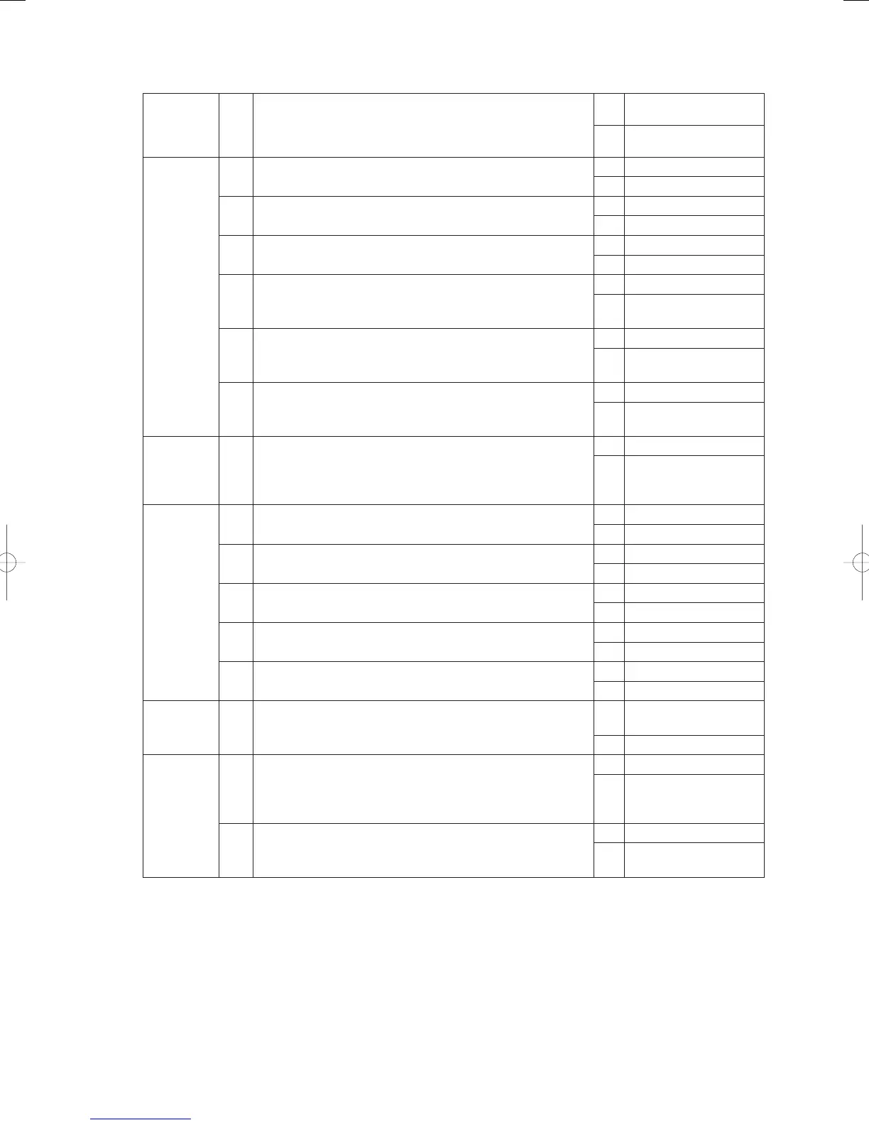
2) When the water heat exchanger unit is connected
1
Remote
controller
power
1-1 Is power being supplied to the remote controller?
Yes 2-1
No Switch on the power
2
Remote
controller
(parallel
array)
address
2-1 Has an address been set on the remote controller?
Yes 2-2
No Set the address
2-2 Is the address set in the remote controller in series?
Yes 2-3
No Set a serial number
2-3
Do the address on the remote controller and on the water heat
exchanger unit match up?
Yes 2- 4
No Match up the addresses
2-4
Does the number of addresses on the remote controller match
up with the number of water heat exchanger units?
Yes 2-5
No
Match up the number of
connected units
2-5
Is the parallel array address on the water heat exchanger unit
set at anything other than [0]?
Yes 2- 6
No
Set any parallel array
address other than [0]
2-6
Is the parallel array address on the water heat exchanger unit
set at [1 - 5]?
Yes 3 -1
No
Set the parallel array
address at [1 - 5]
3
Terminal
resistor
3-1
Are the terminal resistor switches on the remote controller and
on water heat exchanger unit’s control board located at both
ends of the wire linking the remote controller with the water
heat exchanger unit set at ON?
Yes 4-1
No
Set the terminal resistor
for both ends of the link
wire to ON
4
Remote
controller
wires
(wires
linking
between
the remote
controller
to the
water heat
exchanger
unit)
4-1
Is the remote controller’s wire severed (connector or terminal
disconnected?)
Yes Repair the severed wires
No 4-2
4-2 Is the remote controller’s wire short-circuited?
Yes Repair the short-circuit
No 4-3
4-3 Is the remote controller’s wire grounded?
Yes Repair the ground
No 4-4
4-4 Is the remote controller’s wire polarity (+-) reversed?
Yes Switch the wires around
No 4-5
4-5
Are the remote controller wire (TB5-4, TB5-5) and outdoor
unit wires (TB1-
,
) connected to the wrong places?
Yes Repair the wiring
No 5-1
5
Noise
5-1 Is a source of noise located nearby?
Yes
Set up noise
countermeasures
No 6-1
6
Remote
controller or
peripheral
equipment
6-1
Have the settings been made in accordance with the remote
controller’s instruction manual?
Yes 6 -2
No
Repair the settings in
accordance with the
instruction manual
6-2
Does a repairable fault exist in the remoter controller or
remote controller board?
Yes Restore
No
Replace the remote
controller
● For board and Electrical Wiring Diagram, see Chapter 6.
• Outdoor main board: page VI-2
• Outdoor power board: page VI-3
• Converter board: VI-4
• Indoor control board for DC motor models: page VI-5
• Outdoor Unit Electrical Wiring Diagram: page VI-6
GHPtroubleshooting.indbIV‒36GHPtroubleshooting.indbIV‒36 2012/11/2611:20:092012/11/2611:20:09