IV–8
3-4
Is approximately AC200V applied between the magnet switch’s No. 2
and No. 6 when the magnet switch is turned on?
Yes 3 - 5
No 3-6
3-5
Are there any defective wiring connections/contacts or severed wires between the magnet
switch and the starter power source’s relay connector 2P-6 (white?) → Repair wiring
3-6
Is approximately AC200V being applied between the magnet switch
No.1 and No.5?
Yes 3 -7
No
Check primary
wiring→ Repair
3-7
Is approximately AC200V applied between the magnet switch A1 and
A2 when the magnet switch is turned on?
Yes
Replace the
magnet switch
No 3-8
3-8
Are there any defective wiring connections/contacts or severed
wires between the outdoor unit’s power board connector 3P (yellow)
CN028 and the magnet switch?
Yes Repair Wiring
No 3-9
3-9
Is approximately AC200V being applied between the outdoor unit’s
power board connector 3P (white) CN002 No.1 and No.3?
Yes
Replace the
outdoor unit’s
power board
No
Check the
relevant wiring
and fi lter board
4
Starter/
starter relay
(outdoor unit
main board)
4-1
Is DC10V or more applied between the starter B terminal (+) and
engine ground (-) when the magnet switch is on?
Yes 4-2
No 4-3
4-2
Is DC10V or more applied between the starter S terminal (+) and
engine ground (-) when cranking is started?
Yes
Replace the
starter
No 4-5
4-3
Is DC10V or more applied between the starter power source (+) and (-)
when the magnet switch is on?
Yes 4- 4
No 3-3
4-4
Are there any defective wiring connections/contacts between the starter power source’s +
terminal and the starter’s B terminal, or between the starter power source’s - terminal and
engine ground? → Repair wiring
4-5
Is DC10V or more applied between the outdoor unit’s power board
connector CN084 (+) and the outdoor unit’s main board connector
FG CN075 (-) when cranking is started?
Yes 4- 6
No 4-7
4-6
Are there any defective wiring connections/contacts between the outdoor unit’s power board
connector CN084 (+) and the starter’s S terminal? → Repair wiring
4-7
Is DC10V or more applied between the outdoor unit’s power board
connector CN084 (+) and the outdoor unit’s main board connector
FG CN075 (-) when the magnet switch is on?
Yes
Replace the
outdoor unit’s
main board
No 4-8
4-8
Are there any defective wiring connections/contacts between the outdoor unit’s power board
connector CN084 (+) and the starter power source’s + terminal? → Repair wiring
● For work procedure for replacing outdoor main board, see “5. Reference Document”.
● For board and Electrical Wiring Diagram, see Chapter 6.
• Outdoor main board: page VI-2
• Outdoor power board: page VI-3
• Converter board: VI-4
• Indoor control board for DC motor models: page VI-5
• Outdoor Unit Electrical Wiring Diagram: page VI-6
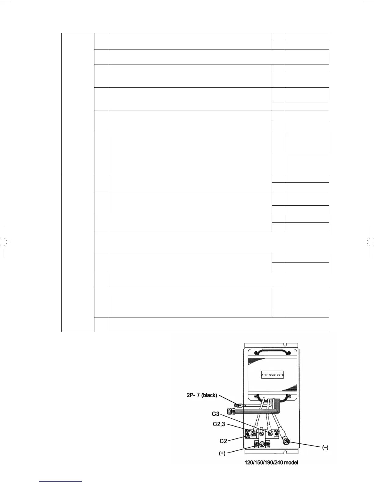
● 3-1~3-5, 4-3, 4-4, 4-6, 4-8
GHPtroubleshooting.indbIV‒8GHPtroubleshooting.indbIV‒8 2012/11/2611:20:062012/11/2611:20:06