IV–98
15-5
Are there any poor connections or severed wires in the wiring
between the outdoor unit’s main board and relay board?
Yes Repair wiring
No 15-6
15-6
Check the relay board.
Does an output voltage (AC 200 V) from discharge valves 1-1,
1-2, discharge valve 2, suction valve 2-1 and 2-2 exist with
“v_open” (valve open) in the No. 4 test mode?
Does suction valve 1 output voltage (AC 200 V) during cooling
operations?
Yes 15 -7
No
Replace the relay
board
15-7
Check the solenoid valve coil.
(The power must be turned off before starting work.)
Disconnect the connectors of the discharge valve 1-1, 1-2,
discharge valve 2, suction valve 1, suction valve 2-1 and 2-2
from the relay board and measure the resistance between No.
1 and 3.
Normal values (20°C): Discharge valves 1-1, 1-2: 543 Ω,
Discharge valve 2: 1,132 Ω
Suction valve 1: 1,197 Ω, Suction valves 2-1, 2-2: 543 Ω
Is the coil operating normally?
Resistance
normal
Replace the
solenoid valve
Resistance
abnormal
Replace the
solenoid valve’s
coil
● See instructions packaged with servicing indoor board for procedure on replacing indoor control board.
● See “5. Reference Document” for details on the procedure for replacing the water heat exchanger unit’s
control board.
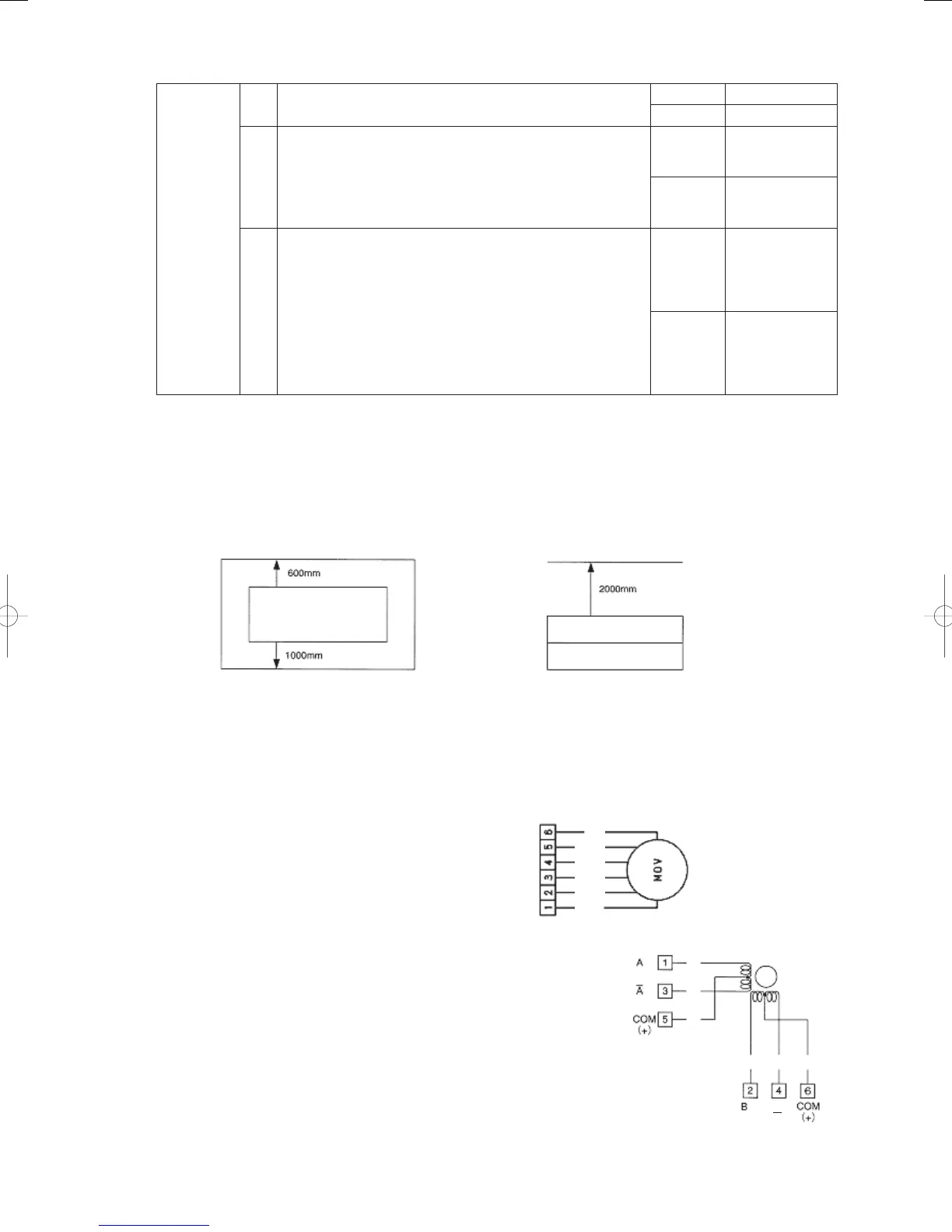
● 2-2
Any air shortage?
An air shortage is likely if the installation conditions pictured below are not met.
Unit perimeter Unit top
or more
Refrigerant tubing
Front
or more
or more
● 6-1
Indoor electric valve check
Electric valve opening determination standards:
During heating operation, after 30 minutes have passed in complete combustion, the
indoor coil outlet temperature must exceed 40°C.
Check using No.0 Operation data display.
Orange Yellow Gray
Red Black White
● 6-2
Normal if a pulse voltage is applied across indoor control board
connector PMV 6P (white) CN082 No. 5 and No. 1-4 after turning
power ON. (About DC4V measured on tester)
● 6-3
Unplug indoor electric valve connector 6P (white), and measure
resistance of electric valve coil between No.5 and No.1-4 using a
tester. Replace coil if 0Ω or ∞ (46Ω is normal).
Phase
Phase
Gray Yellow Orange
Red Black White
Phase
Phase
B
GHPtroubleshooting.indbIV‒98GHPtroubleshooting.indbIV‒98 2012/11/2611:20:152012/11/2611:20:15