Operation Manual
FT128 Rev 2.4
27
relay is controlled by the “Voltage output S0”
20
e.g. if S0 is programmed for general alarm,
the following outputs will be available:
• Voltage output S0 on CON 7
• Change over alarm contacts R2-1 on CON 5
• Change over alarm contacts R2-2 on CON 6
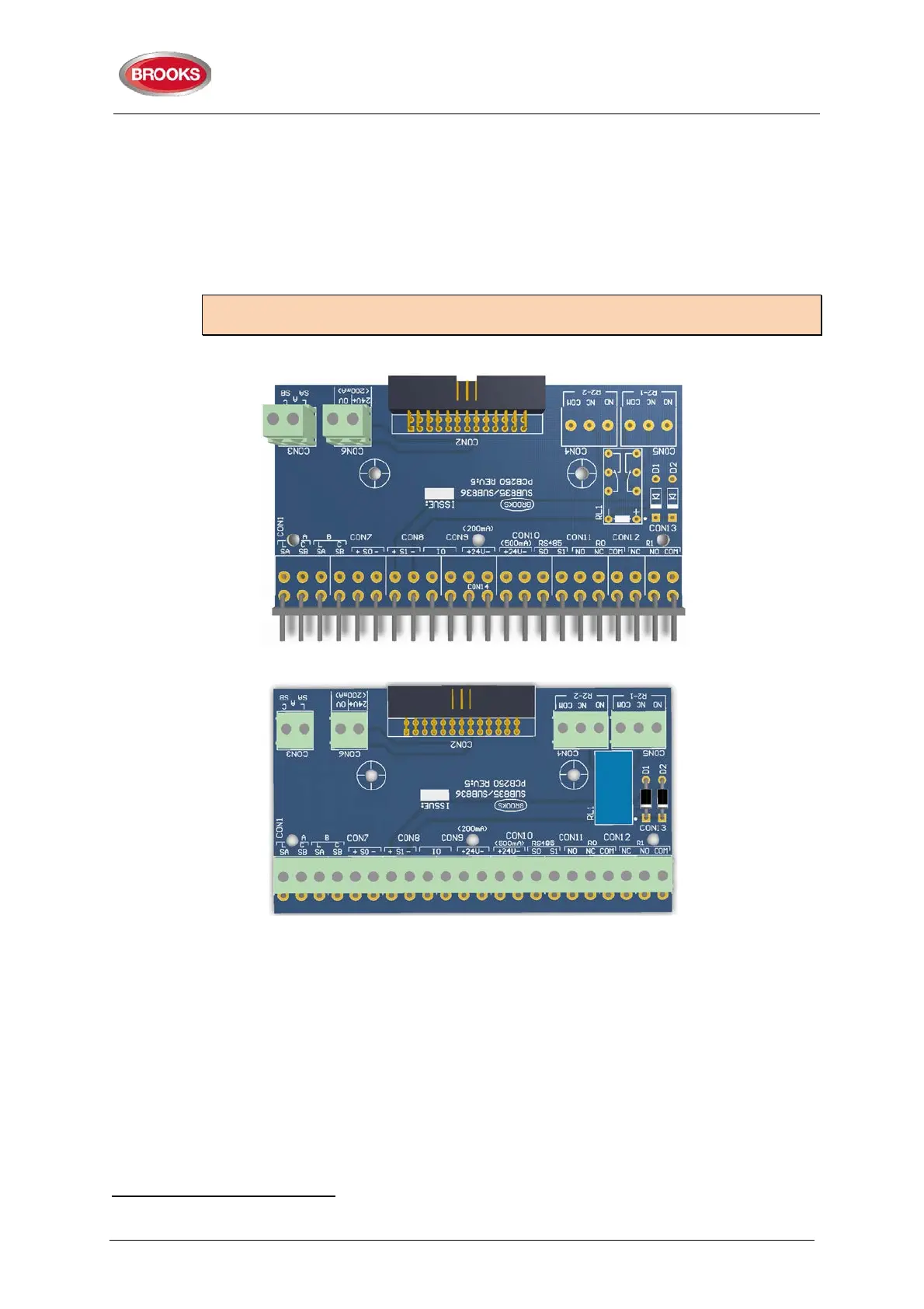
The PCB layout of the adapter board SUB936 is shown in Figure 9 below.
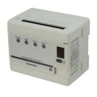
The PCB layout of the external termination board SUB835 is shown in Figure 10 below.
Note: As shown in Figure 9 and Figure 10, one actual PCB is used for both boards with
different components fitted in each one.
Figure 9 SUB836 Adaptor Board
Figure 10 SUB835 external Terminal Board
The adapter board SUB836 provides additional terminals to support connections of COM
loop (CON 3) and 24V (CON 6) to I/O matrix boards 4582 mounted on the front door.
The external termination board SUB835, as shown in Figure 10, provides the two additional
alarm relay contacts R2-1 and R2-2 (CON4 & CON 5), current rating for the contacts is 2A
@ 30V
DC
. The SUB835 provides additional terminals as well for the COM loop and 24V
DC
,
these terminals can be utilised for modules mounted on the equipment plate and requiring
COM loop connections or 24V
DC
.
20
The voltage output V0 terminals are still available on the termination board SUB835 please note, the current limitation of V0 is
less than 200mA.