Operation Manual
FT128 Rev 2.4
30
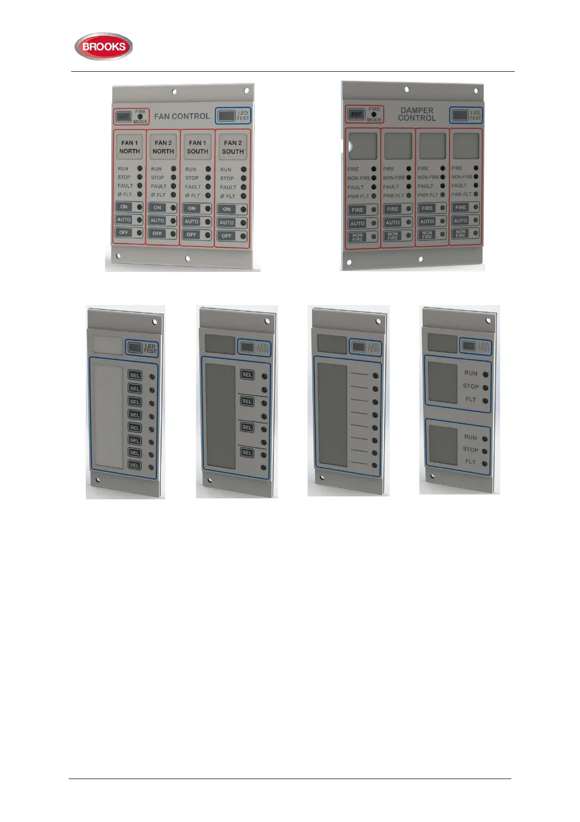
Figure 15: 1206 Fan Control Module
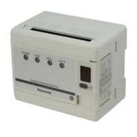
Figure 16: 1211 Damper Control
Module
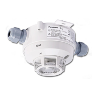
Figure 17: 1207– 8
Key / 8 LED Control
& Display Module
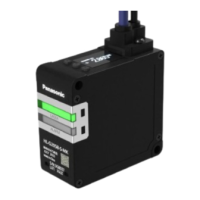
Figure 18: 1208 - 4
Key / 8 LED Control
& Display Module
Figure 19: 1209 – 8
LED Display
Module
Figure 20: 1210 – 6
LED Pump Status
Module
Each display module is manufactured of 3 parts: PCB, plastic spacer and decal label. The
following is a brief description for each display module:
• 1204 – Power Monitor module, designed as an interconnection point between a
rack of new display modules and the FT128. One module per ancillary rack
required and uses a reserved slot (first slot). The module supervises the rack
power that feeds 24V and 5V to the display modules. Requires 4HP space at the
beginning of the ancillary rack and one COM loop address.
• 1205 – 15 Zone Display and Control module, which is an upgrade over the old
4582/SUB900 Zone Display combination. In EBLWin, the 1205 still is programmed
as an “I/O matrix board 4582” for “Zone Control”. Require 2 x 10HB spaces on the
ancillary rack. Internally connected to COM loop 0 similar to expansion boards
458x. Refer to the limitation of 4582 in Table 3 page 14.
• 1206 – Quad Fan Display and Control Module, which is an upgrade over the old
4582/SUB902 Fan Display combination. In EBLWin, the 1206 still is programmed
as an “I/O Matrix board 4582” for “Fan / Damper Control”. Requires 2 x 10HB
spaces on the ancillary rack. 1206 can connect to any COM loop 0-3, refer to the
limitation of 4582 in Table 3 page 14.