Operation Manual
FT128 Rev 2.4
23
refer to the Technical / Programming manual and to drawing no. F665 in Figure 27 page
145
Disable
Disable
DisableDisable
Disable
Disable
DisableDisable
Disable
Disable
DisableDisable
LED
Test
DS DSDS
DS DSDSDS
DS DSDSDS
AL ALAL
AL ALALAL
AL ALALAL
FT FTFT
FT
FT
FTFT
FT FTFTFT
ZONE CONTROL
DS
AL
FT
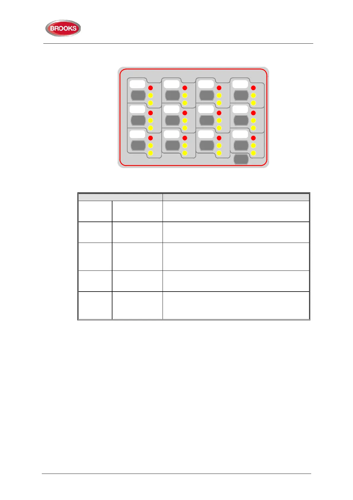
Figure 5 Zone Control & indication Display
Table 9 Zone control LEDs and Buttons
AL
Alarm – Red
1-12
Illuminates when an alarm from a conventional zone
or an addressable device or group of addressable
devices designated as a zone enters an alarm state.
DS
Disable-Yellow
1-12
Illuminates when a zone is disabled either by the
disable switch on the zone control card or where the
zone is disabled via menu H2/B1
FT
Fault – Yellow
1-12
Illuminates when either a short circuit or open circuit
fault on conventional zone or any fault that prevents
an addressable alarm point in a designated zone to
Disable
Button
1-12
Pressing the disable switch will disable the selected
zone. Pressing the switch a second time will re-
enable the zone. Functions same as menu H2/B1.
LED Test Button
Is selectable to be activated either from the FDCIE or
at the Zone Control Module itself, this feature can be
utilised when the module is mounted externally via
4.4 NZ Fire Brigade (LED) Mimic Board
The generic feature in EBLWin software supports the mimic applications of the I/O matrix
board 4582. This feature is used in the New Zealand fire brigade mimic panels or the
standard index panels.
Each NZ mimic board provides 12 LED indicators and screw terminals for 4 inputs
(switches). The first 3 LEDs used for Normal (green), Defect (yellow) and common alarm
(red). The remainder 9 LEDs (red) used to indicate separate zone alarm indications or
sprinkler flow switch indication. Two of the four inputs are used to interface the Bulgin keys
to the FDCIE. Additional mimic boards provide 12 red LED indicators for each board.
Up to 4 mimic boards can be interfaced to each I/O matrix board 4582 to provide
indications for up to 48 LED’s, up to two I/O matrix boards can be used in the NZ mimic
applications, if no zone control modules used. Total number of LED indicators that FT128
can provide is 96 indicators.
The new design of NZ mimic boards provides an option to allow for remote mounting of
LED’s via screw terminals. This can be used (if required) to mount individual LEDs on a
building layout.
Figure 6 below shows an example of a mimic display used in conjunction with FT128 in
New Zealand Steel.