Operation Manual
FT128 Rev 2.4
26
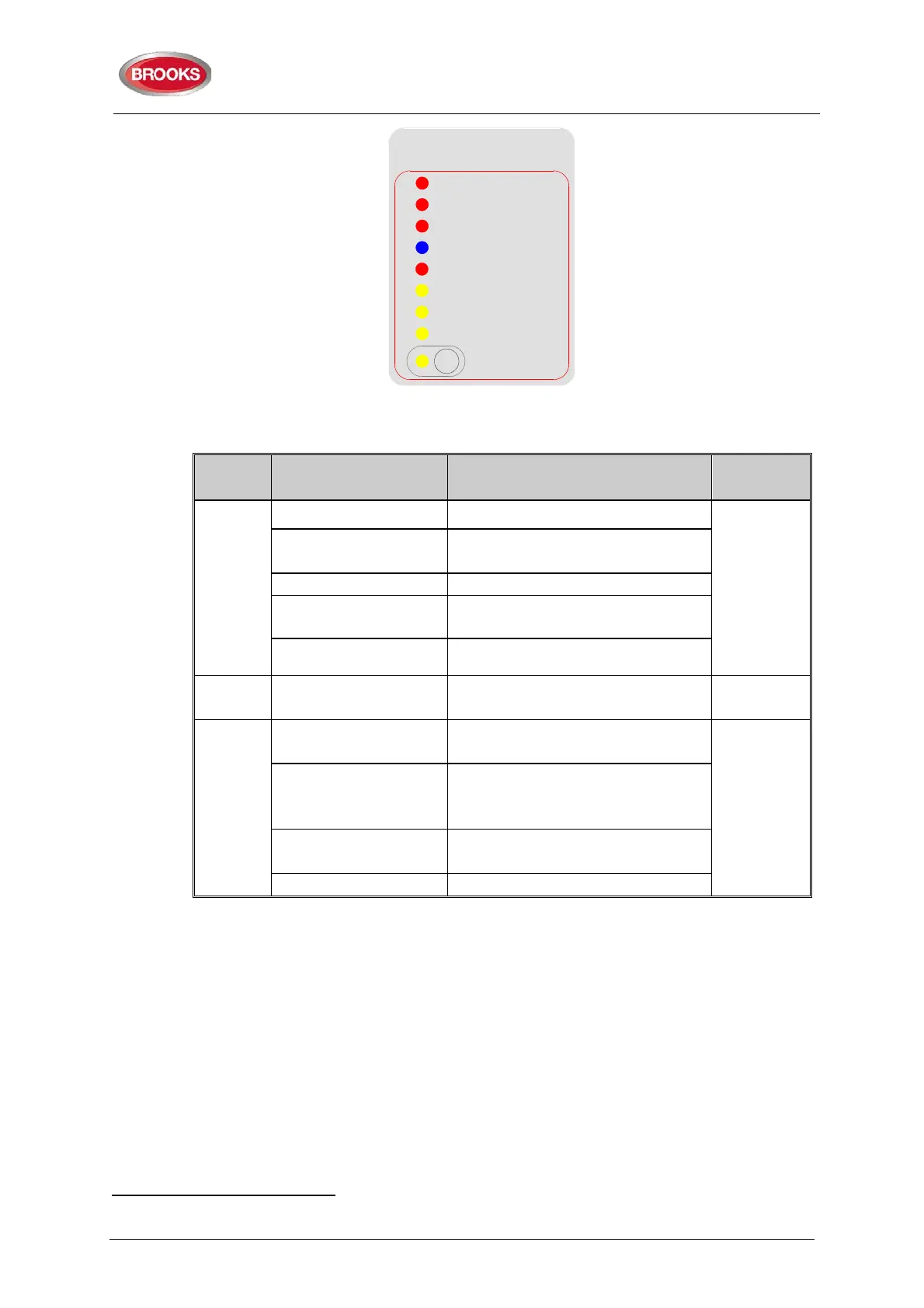
Figure 8 Gas Extinguishing Display Layout
Table 11 Gas Front Status LED Indication and flash Pattern
Type LED Name Module Conditions
LED
Pattern
Alarm
1st Alarm - Red One zone or zone address in alarm
Fast Flash
2nd Alarm – Red,
Timer Running
Both zones or zone addresses in
alarm
Gas release output activated
Gas Externally
Released - Red
External gas release control
activated
Gas Discharged - Blue
Gas discharged sensor input
activated
Fault Gas Fault - Yellow
Fault in any of the supervised
inputs or outputs
Steady ON
Disable
Gas Discharge
Inhibited - Yellow
Gas discharge inhibited via LCS
isolate switch
Steady ON
Gas Discharge
Disabled - Yellow
Gas discharge disabled by the
service master abort switch or the
gas lock-off valve controls
Service Switch Active-
Yellow
Illuminates when the master abort
switch is activated
Gas service master abort switch
4.7 FT128 External Termination
The FT128 Main Board 4556 is normally mounted on the rear of the front door. In order to
avoid the field wiring termination on a swing door, an adapter board SUB836
19
is
connected to the main board. The new version of the adapter board is plugged in the screw
terminals of the 4556 board and interfaced to another external termination board SUB835
mounted on the equipment plate. The adapter board SUB836 is connected to the
termination board SUB835 via ribbon cable.
The FT128 has only one programmable relay. To increase the number of programmable
relays in the standard FT128 system, another relay with two changeover contacts is added
to the termination board to provide 2 sets of additional changeover relay contacts. The
19
The adapter board shown in Figure 9 and external termination board shown in Figure 10 use a new PCB revision (PCB250
Rev 5). In all previous revisions, the adapter board is soldered in the terminals of FT128 main board (4556).
Gas Extinguishing
2nd Alarm -Timer Running
Gas Fault
Gas Discharged
Gas Initiated
Gas Disabled
1st Alarm
Gas Discharge Inhibited
Gas Externally Released
Service
Master Abort