Operation Manual
FT128 Rev 2.4
73
17 Commissioning an FT128
No connection, other than the mains power supply should be made, prior to checking the
operation of the FDCIE
Mains power should be turned on and charger voltage levels checked / set. If these levels
are correct, batteries can then be connected. Follow the procedures shown below in 1-9.
Basic operation of the FT128 should be confirmed as supplied without any external
connections, ensure no earth fault shown on the LCD.
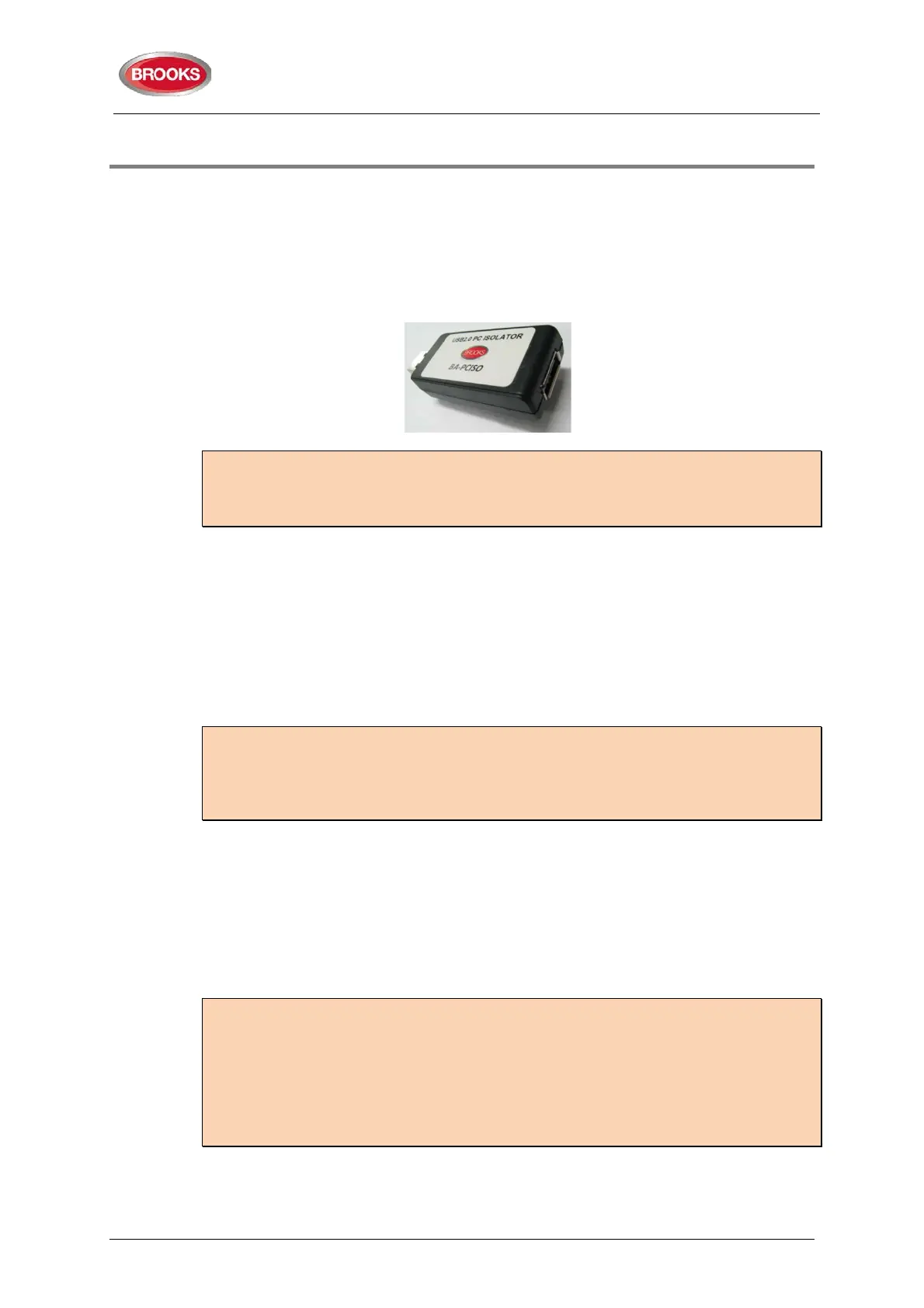
Note: To avoid generating earth fault when connecting a PC to FT128, it is strongly
recommended that Brooks USB isolator BA-PCISO be used. If no isolator is used and if
there are several earth faults in the system when a PC is connected, damages may result
on both PCBs and the PC.
The only “fault” seen by the system, which cannot be fixed at this point of time, should be
“Cut-off COM-loop”. This is due to some loop units e.g. panel MCP, I/O matrix boards,
Panel display modules, etc. in FT128 being wired to the COM loop as Class “B” wiring (no
loop return wiring used). In NZ control panels the MCP mounted on the outer door may be
replaced by the fire brigade Bulgin keys if required.
Before connecting any field wiring, the battery supply and mains power must be
turned off.
Cable resistance readings and field connections must then be checked to ensure they are
correct prior to their connection to the FDCIE
Tip: Measure the resistance of each loop wire (L & C respectively) before turning on the
power. Check that the L-wire (SA) that goes out on CON 1, terminal 1 comes back at
CON 1, terminal 3 and so on. If the loop has short circuit isolators, only the C-wire (SB)
can be measured. Also measure the resistance between the loop wires and 24V, 0V and
Earth. The resistance should be very high (mega ohm).
Power up Procedures:
Once the cabinet is mounted and secured in place, the following power up procedures
must be followed:
1. Connect the incoming mains power feed to the GPO, ensure the mains isolator
switch is “OFF”.
2.
Turn “ON” the incoming mains power from the circuit breaker in the switch
board.
Note: It should be connected to a household removable fuse for the fire alarm FDCIE
only, via a two-way circuit breaker.
The mains cable should be securely clamped and the wires be as short as possible, use
cable ties to keep mains wires well separated from 24VDC wires. The mains safety earth
(ground) should, however, be longer than the other wires, to ensure that it is the last to
be disconnected if the mains cable clamp should fail.
After the installation, the lid protecting the power supply screw terminals should be
correctly applied.
3. Remove the battery fuse F2 on the main board 4556 (or the in-line fuse between
batteries).
4. Connect the batteries to the battery leads.